I was reading the amp repair tutorial about testing either output or power supply transistors, do I need to remove the transistors from the board to isolate them from the others?
I had read somewhere that if a bad transistor is the same circuit it will
give bad readings.
I had read somewhere that if a bad transistor is the same circuit it will
give bad readings.
For definitive results, you must remove them. You can generally find shorted transistors in the circuit. If the shorted transistor is in parallel with other transistors, all of the paralleled transistors may appear shorted until you remove the shorted one.
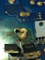
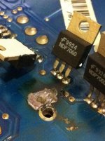
Waiting on the meter to arrive. In the meantime I took a really close look and found a small single strand (1/4"-3/8"long) of what looks like my speaker wire in the area of the damage(The wire is burnt to hell). Not sure if that had anything to do with it, but I'm pretty sure this failure was caused by external sources or by my over tightening the mounting screw that obviously grounded out(see pics). You can see on the second transistor at the top there is a little black spot where the transistor contacted the mounting screw
Anyway I was wondering what is the best way to repair the board where the covering is blown/burnt off?
Anyway I was wondering what is the best way to repair the board where the covering is blown/burnt off?
Attachments
Last edited:
As long as the board is not soft and is flat, it doesn't need to be repaired.
If the screw contacted the tab of the transistor, the wire was irrelevant.
If the screw contacted the tab of the transistor, the wire was irrelevant.
"If the screw contacted the tab of the transistor, the wire was irrelevant."
My thoughts exactly
My thoughts exactly
I was going to buy the Full Access to: Basic Car Audio Electronics listed at $14.95 but then I saw a different link to: Learn To Repair Car Audio Power Amplifiers listed at $49.95 . Now I am a little confused to which one I should be getting. I have no problem with getting either one, I just want to get the correct one the first time.
If it makes any difference I do not have a scope, just the fluke 11 when it shows up. I am just doing this as a hobby and not a career.
Thanks again for your input
If it makes any difference I do not have a scope, just the fluke 11 when it shows up. I am just doing this as a hobby and not a career.
Thanks again for your input
Last edited:
The $15 item was a more complete version of the site but due to all of the updates that have been done and will be done over the next year, I only recommend that people purchase it if they want to donate to the site (because it's not updated).
The repair tutorial on the site is $50+ shipping. If you have more questions regarding the tutorial, email me. The mods don't like people selling items from this forum.
If you found a page where you saw the $15 item and it didn't have a note saying that it was not the repair tutorial, please post the link so I can update it.
A scope will make it much easier to get help and to see what the various signals look like. Send me links of scopes that you're interested in and I'll try to help you get one in good working order. Email me the links, don't post them here unless you want more competition bidding on it.
My Fluke 11 showed up today and seems to work fine. Sweet deal for $25 bucks!
After going over the power supply transistors they all seem to read "good". I know you said that they should be removed to get definitive results, but is it possible that the short caused by the mounting screw did not harm the components and just blew the fuse?
I will post the meter results after work later tonight. I will also attempt to power the amp up via a 2 ohm high-power resistor (25-100 watt resistor).
Thanks again.
Here are the test results of the four power supply transistors using the NPN transistor test proceedure in the Basic Amp Repair Tutorial.
Test #1
(+ on gate - on drain)
(1) -.598
(2) -.582
(3) -.576
(4) -.559
(+ on gate -on source)
(1) .125
(2) .125
(3) .125
(4) .125
Test #2
(+ on source - on gate)
(1) .125
(2) .126
(3) .126
(4) .126
Test #3
(+ on drain - on gate) When testing these the meter climbed steadily to somewhere around 2.something then read OL
(1) OL
(2) OL
(3) OL
(4) OL
Test #4
(+ on source -on drain)
(1) .461
(2) .461
(3) .461
(4) .461
Will post output transistors later tonight.
I made a rookie mistake by assuming that the visibly burnt area was automatically the damaged section. Upon further inspection I am getting bad readings in a different power supply that shows no visible damage.
Test #1
(+ on gate - on drain)
(1) .126
(2) .126
(3) .126
(4) .126
(+ on gate - on source)
(1) .126
(2) .126
(3) .126
(4) .126
Test 2 & 3 had same results as previous post
Test#4
1. OL
2. OL
3. OL
4. OL
I will have to pull them to test individually.
Test #1
(+ on gate - on drain)
(1) .126
(2) .126
(3) .126
(4) .126
(+ on gate - on source)
(1) .126
(2) .126
(3) .126
(4) .126
Test 2 & 3 had same results as previous post
Test#4
1. OL
2. OL
3. OL
4. OL
I will have to pull them to test individually.
Attachments
Why do you think these readings indicate that there is a problem?
I am probably assuming stuff again.
It was the only one out of all four power supplies that read differently. The other 3 had nearly the exact same numbers as post #30. New sill pads should arrive later today. I'll get it put back together and test.
When you have a decimal value, always use a leading zero. A single pixel on a dark background is difficult to see (and I didn't see it). I thought it was 125 ohms.
I see that there is a difference now. In the future, you may want to copy and paste the original measurements then, on the side of the original measurements, include the ones that are different.
Did you check the drivers? You may have one that's shorted.
Where did you find suggestions for testing transistors with 4 steps?
Sorry for the confusion. Next time I will post a zero before the decimal.
This is the page I used for the NPN test proceedure.
Speaker Load and Amplifier Failure
I will check the output drivers today. I'm having a hell of a time tracking the traces to see which ones go to this power supply.
This is the page I used for the NPN test proceedure.
Speaker Load and Amplifier Failure
I will check the output drivers today. I'm having a hell of a time tracking the traces to see which ones go to this power supply.
The tests on all pages are for transistors out of the circuit. The readings in the circuit will be much different.
You stated that you were going to check the output drivers. I assumed that this was for the power supply, not the audio section of the amp.
The tests for the bipolar transistors (NPN/PNP) are different than those for FETs. In the circuit it doesn't matter much because you're generally only looking for a 0 ohm reading. Out of the circuit, you have to use the right test procedure. In the future, use the procedures and applets on the basic transistor testing page (in sig line) if you test the transistors out of the circuit.
Hello again! Well I gave up and took it to a local shop due to the fact that I didn't have any kind of a schematic, and I really don't know what I'm doing. Anyway after 2mo. In the shop he tells me that w/o a schematic he won't be able to fix it. He told me he had one on his PC before I ever took it to him. (A-hole)!
Can you recommend a good repair shop or person that may be willing to repair it? I am willing to ship anywhere in North America. Thanks
Can you recommend a good repair shop or person that may be willing to repair it? I am willing to ship anywhere in North America. Thanks
Last edited:
- Status
- Not open for further replies.
- Home
- General Interest
- Car Audio
- Perry, I need your help!