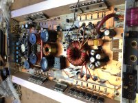
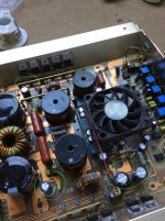
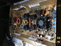
I’ve gotten this amp to repair, an unmounted board test reveals shorted outputs, shorted power supply and blown input dc caps.
My main concerns are it was already repaired and I want to restore it, also there are a lot of factory glue that needs cleaning as I see corrosion.
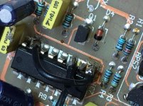
There’s a board that’s mounted on the B+ and GND terminal with one wire to the TL494 IC (is it a part of the protection circuitry?).
Is there any available schematic diagram for this particular amp or something naturally close? I need to identify some parts I think that were used in this amp by the previous tech.
My main concerns are it was already repaired and I want to restore it, also there are a lot of factory glue that needs cleaning as I see corrosion.
There’s a board that’s mounted on the B+ and GND terminal with one wire to the TL494 IC (is it a part of the protection circuitry?).
Is there any available schematic diagram for this particular amp or something naturally close? I need to identify some parts I think that were used in this amp by the previous tech.
Attachments
Can that board be anything more than an under/over voltage protection (unless it has a thermistor on it somewhere)?
I have a few photos. If you tell me specifically what you need to see, I'll see if I have a photo showing them.
I have a few photos. If you tell me specifically what you need to see, I'll see if I have a photo showing them.
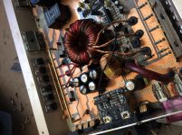
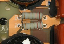
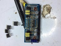
Yes Mr Babin, the resistor RP41 is burnt would link to know the value, and there is modifications around QE5 also want to know the part number or what’s the purpose of the modification in that part of the power supply, and there’s a jumper on the TL494 (one of the attached wire is from the board that’s fitted across the input terminals B+ and GND.
Attachments

Is there any other mosfet to sub the FQP12P20 as I can’t get those from my local supplier also what would compliment to the FQP19N20 or also a sub for it.
I don't know of any subs. Maybe someone else has tried and confirmed that something else will work reliably.
I see Rochester has what appear to be legit FQA12P20 devices.
Rochester Electronics
: Search for 12P20
I've not ordered from them.
I was sent some FQA19N20 devices 2 weeks ago from an out-of-country supplier that has an excellent reputation, but they clearly looked fake to me. Sent them back, though he still claims they are legit and meet specs.
Rochester Electronics
: Search for 12P20
I've not ordered from them.
I was sent some FQA19N20 devices 2 weeks ago from an out-of-country supplier that has an excellent reputation, but they clearly looked fake to me. Sent them back, though he still claims they are legit and meet specs.
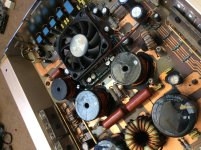
....amp was repaired, work flawlessly for 2 months, customer returned it (he mounted it on the bass box and one of the output inductor become loosed) one output fet shorted FQP12P20 taking down the replaced power fet IRF3205 which was installed by me, all the original parts are still up and running. The problem im having now after all the latest replacements is im having a thump sound when power on or off the amp, on isnt as bad but off i see my voltmeter registering 60 volts when i remove the remote and as the relay disengaged. on and idle all fets are super cold but if i cycle the remote power even without speakers you can feel the fets getting warmer after every turn off.
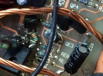
....and Mr Perry, the modification was done to keep the relay closed, but when i asked the customer about if he is having drain battery at sometimes he said yes. The previous tech mods would caused the relay to constantly engaged as long as you mount the amp and have B+ and Gnd.
The amp is not switched on that way but the relay would be ever on all the time, ive removed the mods and it is turning on then a 2 second delay for the relay to kick in. im not sure if the switching of the relay is causing the thump sound as ive jumpered the relay pads and the sound is still there, i was thinking of just remove the relay to see if its a contributing factor, but i definately dont want to have it switched on permanently by the modification if it is even the problem which i very much doubt tho.
Let me know what you think.
Attachments
I am getting a pop, i have no idea. is there any fixed setting on the relay circuit that should open the relay before the system is actually "off" as its delayed when turning on the amp (about 2 seconds click when remote is been applied) it closes?
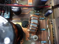
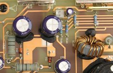
Im currently ordering some caps for the op amp voltages and caps CX6 and CX7 i havent replaced them yet to do more tests.
Could you tell me the value of resistor RA10 and RA11? (is it 2.2ohms or 3.3ohms)?
Im currently ordering some caps for the op amp voltages and caps CX6 and CX7 i havent replaced them yet to do more tests.
Could you tell me the value of resistor RA10 and RA11? (is it 2.2ohms or 3.3ohms)?
The amplifier is fine now, the four caps I ordered makes it right I think there was a swing or a spike in the voltages either on the opamp rail (35v 1000uf) or the smoothing rail caps (200v 33uf) when the amp powers on or off.
Is there any know tester or test procedures that can use to definitely know when a cap is bad? As fixing this amp the capacitors was tested good on my Fluke 115 and also my capAnalyzer? And too many times I’m been thrown off by bad caps that just simple reads good.
Is there any know tester or test procedures that can use to definitely know when a cap is bad? As fixing this amp the capacitors was tested good on my Fluke 115 and also my capAnalyzer? And too many times I’m been thrown off by bad caps that just simple reads good.
Attachments
It’s here again this amp has ran aground, owner loss my contact and send the amp to another technician, and few key parts been missing and some replaced, does anyone has an schematic diagram for this amp or even for the output section along with the driver board?
Needed the output installation location I know they are P types with N types 19N20 and 12P20.
Also a detail rebuilt of the audio driver board.
Needed the output installation location I know they are P types with N types 19N20 and 12P20.
Also a detail rebuilt of the audio driver board.
Attachments
Have you seen this thread?
Again with the Dlogixs DLM4500
What do you need to know about the main board? There isn't much on it.
Again with the Dlogixs DLM4500
What do you need to know about the main board? There isn't much on it.
Good day guys, does anyone have a schematic for the mainboard of this amp?
Or can assist me in knowing what part goes QA2, QA4, QA6, QA8
And QA1, QA3, QA5, QA7, QA9 respectively
They are 12P20 and 19N20..
How do I read the circuit of the amp to know how to place the Ntype and Ptype mosfets?
Or can assist me in knowing what part goes QA2, QA4, QA6, QA8
And QA1, QA3, QA5, QA7, QA9 respectively
They are 12P20 and 19N20..
How do I read the circuit of the amp to know how to place the Ntype and Ptype mosfets?
I don't have anything on that specific amp but when there are more FETs in one bank than the other, the bank with more FETs is the P-channel bank.
If the output is taken from the drains of all outputs, the P-channel are on the positive rail.
If the output is taken from the drains of all outputs, the P-channel are on the positive rail.
In regards to the audio driver board for this amp, does anyone have the part marking for D3, D11 and D12 (on the underside of the rev 4 board)
- Home
- General Interest
- Car Audio
- Performance Teknique ICBM-9550