Funny question 'if everything else is perfect'. What everything else?
There is distortion all over the place.
The distorted waveform from the 1st tube anode (why doesn't anybody label tubes anymore?) is processed by the 2nd and 3rd tube.
They will add their own distortion. If you're hoping for cancellation, that is never perfect.
Where's the feedback point connected to?
Jan

Yes, IF the input sine is perfect, and IF the circuit is linear (so no harmonics generated), there will be a perfect sine wave,
by the definition of a linear circuit.
But not if it's a real circuit.
by the definition of a linear circuit.
But not if it's a real circuit.
The circuit distortion is on the drawing ...
Jan
Attachments
The schematic of the amp. And there is some distortion and the bias does not stay stable when signal is applied.
Why are you thinking backwards ? First how are the signals at outputs ( anodes ) ? This should be checked without negative feedback applied , it is not clear if you are testing just this circuit or the whole amplifier
They are "perfect".Why are you thinking backwards ? First how are the signals at outputs ( anodes ) ? This should be checked without negative feedback applied , it is not clear if you are testing just this circuit or the whole amplifier
I never checked myself since only the outputs are important 
Maybe is normal for an "imperfect" long tailed pair
Maybe is normal for an "imperfect" long tailed pair
Will there always be a perfect sine wave at the red dot if everything else is perfect? 🤔
Fun fact. The Hewlett Wien Bridge Sine Wave generator was originally done with pentodes because no transistors at the time.
Here is a snippet from Linear Tech AN43.
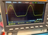
I think if you check the other one, you'll see the negative part of the sine wave. Class AB and all that.This is the waveform I get at the cathode of the 12BH7.
How does the output look?
What bias is unstable?
No disrespect meant but I feel that there's a gap between the complexity of this circuit and your technical expertise. Are you sure this is a good project for you?
Jan
Last edited:
Oh... absolutely correct. That's why I hoped for some help from the diyaudio community, but I also acknowledge that one can lead a horse to water but you cannot make it drink. So maybe it`s better to go back to a "simpler" design.No disrespect meant but I feel that there's a gap between the complexity of this circuit and your technical expertise. Are you sure this is a good project for you?
Jan
Personally I get a lot of joy working with a circuit I understand, and that I can 'play' with and know how to change this or that to get it such and so.
There's no fun in groping around in the dark.
The other thing is that getting to the point that you can run a marathon requires to start with lots of shorter runs several times a week.
Marathon runners are not born, they build themselves.
Just as savvy electronics designers.
YMMV
Jan
There's no fun in groping around in the dark.
The other thing is that getting to the point that you can run a marathon requires to start with lots of shorter runs several times a week.
Marathon runners are not born, they build themselves.
Just as savvy electronics designers.
YMMV
Jan
The design is from Max Robinson`s web site. Its original design is made by Tim E. Smith but uses 12AY7 and 8CG7 as input and driver. Then reworked a bit by Max Robinson.Personally I get a lot of joy working with a circuit I understand, and that I can 'play' with and know how to change this or that to get it such and so.
There's no fun in groping around in the dark.
The other thing is that getting to the point that you can run a marathon requires to start with lots of shorter runs several times a week.
Marathon runners are not born, they build themselves.
Just as savvy electronics designers.
YMMV
Jan
I made mine with EF86 and 12BH7 and sent it to Max Robinson and he approved. Said this could work very well. And it did, for 6 months. Tried all new tubes, changed some components, etc, but no, still wont work. Thought about transformers but they cannot both malfunction at the same time.
Its 2W and I will check.Does the 33K or 39K 1W resistor get warm after use and powered down?
Jan, there is no 'other one'. These cathodes are coupled together. it's not a push-pull output stage, it is a phase splitter. At least I hope so. But the red dot is a very low impedance point looking into the lower triode when it is conducting. Maybe that affects measurement.if you check the other one ... Class AB and all that.
Well, if it stopped working, what are the symptoms? Did it just not power up, are both channels dead, do the tubes light up, did you check the fuse?The design is from Max Robinson`s web site. Its original design is made by Tim E. Smith but uses 12AY7 and 8CG7 as input and driver. Then reworked a bit by Max Robinson.
I made mine with EF86 and 12BH7 and sent it to Max Robinson and he approved. Said this could work very well. And it did, for 6 months. Tried all new tubes, changed some components, etc, but no, still wont work. Thought about transformers but they cannot both malfunction at the same time.
Think about going to a doctor saying 'I don't feel well'. First thing he does is asking all kinds of questions trying to find out what's wrong with you, if anything.
It's an advanced technique called 'diagnosing'; but it seems to have fallen in disgrace with audio people.
Jan
Your schematic in post#5 shows DC voltages. Are these actually measured, or just design center (hoped for)? A pentode loaded by a constant current source is inherently twitchy for idling conditions, and your 12BH7 clipping sure looks like its DC voltages are way wrong. The actual DC voltage at their common cathodes is the first thing to tell us.
Did this ever work, or is it suddenly broken? Important details missing.
All good fortune,
Chris
Did this ever work, or is it suddenly broken? Important details missing.
All good fortune,
Chris
- Home
- Amplifiers
- Tubes / Valves
- Perfect sine wave.