Hello to everyone,
I'm looking for Phantom power 48V made from transformer AC12v ideally or AC 24V.
I would like to use only best available capacitors, resistors, and etc. I would appreciate 1layer board with marked outputs to mic and to mix. I apologise, sometime I just need more details, otherwise I am lost...
If it will have protection relay for the mic that would be huuuuge benefit. And PCB layout would be awesome!
If somebody will help me with few working schemes for simple but HiFi (low noise, total silent, just the pure clean voice from mic) phantom power ready to use for PRO work, then the project I choose build up. And PROVIDER of scheme will get for help: gifts send by post office anywhere in the world 🙂 The gifts are new quality capacitors, new toroidal transformer, new speaker protections, new cables for ac/dc and new HQ cable for microphone, some tools, etc.
I think people has to be motivated. It is another version how to say 'thank you"
Best wishes,
Milan
Last edited:
Hi Milan,
Probably the most important thing when installing Phantom power is not to skimp on the splitting resistors -- you simply must use the recommended 0.1%-matched resistors. Anything less will add noise and cause everything else you do in the power supply to become much more crucial.
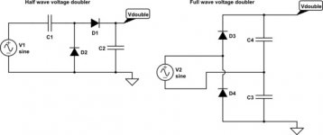
A very easy to build, acceptably quiet, analog Phantom power supply can be made with a small (50 mA/300 mA/or other) 12.6V transformer, 2 cheap rectifiers, and 2 ordinary capacitors, using a popular voltage doubler circuit:
(see below)
Easy huh? Don't get too excited -- it only provides 36 Volts. However, none of the five Neumanns that I've run with it has ever had a problem with that. Expect a slight sensitivity decrease -- if that few dB matters to you, just use an 18V transformer. Plus, sometimes it's helpful: Neumann output can be a little too hot for some boards.
If you're really concerned about noise, you can add an extra R/C filter stage before distributing to the 6k8 splitters at the XLRs. But remember, the very high common mode rejection makes much of the magic of Phantom powering: A few millivolts of 50/60Hz ripple on the supply will never find its way into a good mixer.
The very kind offer of gifts in return for this modest help, while much appreciated, is not necessary -- for me at least -- but thanks for offering.
Best Regards,
Rick
Probably the most important thing when installing Phantom power is not to skimp on the splitting resistors -- you simply must use the recommended 0.1%-matched resistors. Anything less will add noise and cause everything else you do in the power supply to become much more crucial.
A very easy to build, acceptably quiet, analog Phantom power supply can be made with a small (50 mA/300 mA/or other) 12.6V transformer, 2 cheap rectifiers, and 2 ordinary capacitors, using a popular voltage doubler circuit:
(see below)
Easy huh? Don't get too excited -- it only provides 36 Volts. However, none of the five Neumanns that I've run with it has ever had a problem with that. Expect a slight sensitivity decrease -- if that few dB matters to you, just use an 18V transformer. Plus, sometimes it's helpful: Neumann output can be a little too hot for some boards.
If you're really concerned about noise, you can add an extra R/C filter stage before distributing to the 6k8 splitters at the XLRs. But remember, the very high common mode rejection makes much of the magic of Phantom powering: A few millivolts of 50/60Hz ripple on the supply will never find its way into a good mixer.
The very kind offer of gifts in return for this modest help, while much appreciated, is not necessary -- for me at least -- but thanks for offering.
Best Regards,
Rick
Attachments
You should also look into commercial mixer schematics where they ramp slowly the Voltage to prevent thumps on speakers.
Have you seen this? 48V Phantom Feed Supply for Microphones
It has everything you want. It even shows the Wheatstone bridge for matching resistors.
Not sure if this is about DIY for self, commercial hifi, or commercial PA. Execution would be different for each. If I were building it for myself I would ignore this complexity and just use a stacked pair of LM7824's.
Brilliant tip leadbelly! The Elliot Sound Products page does an excellent job covering a range of important stuff.
Big Plus One -- right up to your stacked pair of LM7824's -- that'll need a handful of rectifiers (some perhaps Schottky) to keep the parts safe as power is applied and removed. Some wasted power, too, since the lower device will have something pulling UP on its output terminal, instead of down. How about a 24V zener to steady the reference leg of 'the upper' actual regulator? Simpler, cheaper, more reliable. It'll still need careful design to avoid overvoltage exposure at power-up since very few LM78xx's can withstand seeing more than 40V.
I like ESP's 3 transistor regulator: Nobody (none of the parts) has to risk death at the 'hands' of a filter cap charge or discharge.
MAACO's point is great, too -- sometimes I forget that at most of my gig's we had the luxury of leaving the board off 'til all the mic's were mounted and lashed.
Best Regards,
Rick
Last edited:
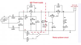
Much love for the venerable MPSA06, but wouldn't a P-ch MOSFET be a better choice? DigiKey shows 36 p/n's, $0.56 US to $1.18, 480mA - 1.3A, SOT-23 et.al. cases, and lots of stock for most of 'em. Then we could reduce the distribution buss from 3 wires/traces to 2, no need for the 72V line at all. A small gate-drain cap to take advantage of the Miller effect -- just big enough to swamp the FET's intrinsic value. Then we could eliminate one wire to the Phantom/NoPhantom switch, wouldn't have to worry about timing cap leakage (ordinary electrolytics are often wide tolerance in value, and leakage from mfg to mfg and batch to batch can vary by 10 or 20 times), or subjecting the pass device to 22V reverse Vbc. As a bonus we'd get a linear, symmetrical ramp -- it wouldn't ramp On faster than Off. Don't forget an 8 or 10V zener, gate-source, to protect the gate oxide.
Surely a board mfg is already doing something similar -- it seems a little too obvious and straight-forward after puzzling it out a little.
Thoughts?
Best Regards,
Rick
Surely a board mfg is already doing something similar -- it seems a little too obvious and straight-forward after puzzling it out a little.
Thoughts?
Best Regards,
Rick
Last edited:
Hello Rick, thanks for help!
I thought I could give some things away, before they will get too dusty 🙂 and ask for help, get some help looks like good way.
I thought I could give some things away, before they will get too dusty 🙂 and ask for help, get some help looks like good way.
You're so welcome! 'Sharing the wealth' (in parts) is surely kind and generous idea, but I'd be awfully surprised if your dust is as thick as mine.
Still -- admire/appreciate your generousity.
Good luck and keep us posted. What a fun diy project. Bet Prague is plenty gorgeous this time of year.
Hopeful Regards,
Rick
Still -- admire/appreciate your generousity.
Good luck and keep us posted. What a fun diy project. Bet Prague is plenty gorgeous this time of year.
Hopeful Regards,
Rick
Oh, just remembered that you asked for boards as well. One other option is to just buy a cheap unpopulated LM317 PCB from China and build it with LM317HV and adjust components accordingly to get 48VDC output.
even with perfect symmetry of the resistors 0.1% or 60dB, the mike cable is mostly not better than 40dB, unless you use a starquad mike cable. the other noise source may be the power transformer injecting mains noise from caused by the primary to secondary capacitance. so toroids are usually worse than conventionals. a dual screeen between primary is best, the primary side screen grounded to mains ground, the secondary screen grounded to audio ground.
- Status
- Not open for further replies.
- Home
- Amplifiers
- Power Supplies
- Perfect Phantom Power - does exist something like that?