The black holes on top are spring mounted fuses, so you don't have to open the amp when you have to change them.
My experience with the construction was smooth. Digikey had sent me the wrong chip at first for LM337 and they had labelled it wrong. After that got sorted out, everything went smoothly, but it's a lot of work soldering those SMD components. I modified a tweezer to hold them securely before soldering. A magnifying light is a must, IMO. Also, once you're done, make sure to clean with rubbing alcohol. The connections are tiny and rosin can easily get to them. I used a toothbrush and rubbed it really good with alcohol.
Well that's it. Back to enjoying them.
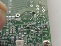
My only point of view here is your input cable.
Personally I wouldn't have unshielded cable so close to a 10 A wideband output. I should at least move them away and/or use shielded cable. If you don't experience any problems of this arrangemant I'll guess this isn't anything to worry about.
Otherwise, have you had any chance to listen to the amp yet?
You don't have to clean the pcb but it looks nicer. I always clean my pcb's especially when I'm going to take pictures.
I use a brush with the brush hair cut short, isopropanol, Yes, and water and comressed air to dry the pcb.
Hello Per-Anders,
I would like to ask what resistor number need to be changed to increase the gain.
Also, what is the formula for calculating the gain?
By the way, my Aksa 55W gain is 38 (31dB).
Thank you.
Enrico
I would like to ask what resistor number need to be changed to increase the gain.
Also, what is the formula for calculating the gain?
By the way, my Aksa 55W gain is 38 (31dB).
Thank you.
Enrico
If you scroll down to the end and look for "Gain" you will find it.
http://home.swipnet.se/~w-50719/hifi/qrp02/schema_qrp02.html
I recommend that you change R4 (lower value).
Total gain is (R5/R4+1)*(R7/R6) = 22.8 (27 dB)
38 in gain (if that is true) seems to be a bit much for normal signal sources but this is only a matter of taste. But you see also that it differs only 4 dB.
peranders said:My only point of view here is your input cable.
Personally I wouldn't have unshielded cable so close to a 10 A wideband output. I should at least move them away and/or use shielded cable. If you don't experience any problems of this arrangemant I'll guess this isn't anything to worry about.
Otherwise, have you had any chance to listen to the amp yet?
No, there is absolute no hum or hiss or anything. I have 95db speakers and with the volume cranked up, without music, it's dead quiet.
I'm still breaking in the amps, but they appear to quite clear and smooth. Good bass too, but I'd like to run them for a week or so before making judgement.
Enrico said:Hello Per-Anders,
I would like to ask what resistor number need to be changed to increase the gain.
Also, what is the formula for calculating the gain?
By the way, my Aksa 55W gain is 38 (31dB).
Thank you.
Enrico
Does the gain need to be increased just a bit, or it's way too quiet. The reason I'm asking is that I run into a case of one of the amps being way too quiet, and figured it out to be C1 not being soldered properly. The C1 cap that I got was bigger than its area and didn't leave much room to solder to the pads. I ended up twisting it a bit.
I don't know what it is with my typing these days. As I read my posts, they are full of typos and missing words. Must be the lead... 🙄
to Enrico and Jamh,
congratulations,I hope my amplifier can be finished at once too🙂
The experience of soldering:
what I used is 0.8mm solder,0.5mm will be better.
these smd components is very small,so must use the tweezers to take them.I have two tweezers,a elbow tweezer and a stanch tweezer which the doctor used,feel very well.
I have fixed one pin of smd component at first with the tweezers while soldering,then the other pins are easy to solder.
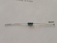
I diy a small spoon(see attached),it can help me to remove any solder excess.
ZANG
congratulations,I hope my amplifier can be finished at once too🙂
The experience of soldering:
what I used is 0.8mm solder,0.5mm will be better.
these smd components is very small,so must use the tweezers to take them.I have two tweezers,a elbow tweezer and a stanch tweezer which the doctor used,feel very well.
I have fixed one pin of smd component at first with the tweezers while soldering,then the other pins are easy to solder.
I diy a small spoon(see attached),it can help me to remove any solder excess.
ZANG
Attachments
I doubt very much that this was your problem because if the cap wasn't soldered properly you wouldn't have got any sound at all.Jamh said:
Does the gain need to be increased just a bit, or it's way too quiet. The reason I'm asking is that I run into a case of one of the amps being way too quiet, and figured it out to be C1 not being soldered properly. The C1 cap that I got was bigger than its area and didn't leave much room to solder to the pads. I ended up twisting it a bit.
If you feel that you can't drive the amp into clipping, you may increase the gain.

peranders said:
I doubt very much that this was your problem because if the cap wasn't soldered properly you wouldn't have got any sound at all.
Yes, but a fact. There must have been just the slightest contact.
thank you Per.
P.S.
I ask for a singapore diyer to help me buy those to-223 packaged lm317/337,I hope to finish this amplifier soon 🙂
About grounding,what suggestions do you have? I find you have put several ground pads on board.
ZANG
P.S.
I ask for a singapore diyer to help me buy those to-223 packaged lm317/337,I hope to finish this amplifier soon 🙂
About grounding,what suggestions do you have? I find you have put several ground pads on board.
ZANG
You have missunderstood the grounding concept. The pcb's are mono blocks. As you see you will have both charging current peaks plus speaker ground plus signal ground in the same wire. You may get good results if you have a thing ground wire between the boards but you must be aware of the you will mix different ground currents. If you can dig up an another transformer all problems are gone.
Peranders,
These monoblocks sound amazing! I've been playing them for 12 hours or so, therefore they're not completely broken in, but already they are wonderful. In particular, the highs are not metallic at all, nice and relaxed. The midrange is not as good as SETs, IMO, but not that far behind. A bit analytical, less sexy. The bass hasn't broken in yet. It is powerful but slightly mushy.
My entire system is Sony SCD-1, Bat Vk3i and home made speakers based on vintage coax Altec Theatre drivers. I ended up modifying the crossover, adding a bit more resistance to the tweeters (4ohm) to make them sound right. It could be due to the fact that my speaker cables are now very short, and less high frequencies get lost in the long cables. Or it could be that the amps are brighter than my 2A3s.
I'm listening to the Mozart Requiem, Tin Hat Trio (highly highly recommended), Boris (from Japan), Kip Hanrahan and Bjork.
All in all, I'm extremely pleased. Many thanks.
Hi Jamh,that is great!😎
a good news,I got those to-223 packaged 317/337 today,I will continue this amp weekend😎
ZANG
a good news,I got those to-223 packaged 317/337 today,I will continue this amp weekend😎
ZANG
Wow.... really amazing.. you can make such beutiful work with ordinary tools .. that's what i call "SKILL"
If you have a good pair of tweezers and two soldering irons it's rather easy to solder all 0805 parts like caps and resistors. You don't have to have a very small iron tip either but for IC's it's good to have a smaller tip.
Normal sodering iron
http://home5.swipnet.se/~w-50674/hifi_pics/hifi_100pr/WS51.jpg
For smaller jobs, finer tip
http://home5.swipnet.se/~w-50674/hifi_pics/hifi_100pr/WS81.jpg
A very good tweezer
http://home5.swipnet.se/~w-50674/hifi_pics/hifi_100pr/tweezers_smd_overview.jpg
Detail of the tweezer tip
http://home5.swipnet.se/~w-50674/hifi_pics/hifi_100pr/tweezers_smd.jpg
For my tweezers, what I did was to bend the ends towards each other so that they are touching with a very small amount of compression force. This way you don't have to hold on to them.
Peranders, one thing I don't understand about your 2 irons is how do you apply the solder. Do you pre-apply it to the iron tips? I mean we humans have only 2 hands!
Peranders, one thing I don't understand about your 2 irons is how do you apply the solder. Do you pre-apply it to the iron tips? I mean we humans have only 2 hands!
I apply solder first at the pads, then place the part, then warm it, then move the irons rather horizontally, then the part sucks into place.
- Status
- Not open for further replies.
- Home
- Amplifiers
- Chip Amps
- peranders industry gainclone assembly progress