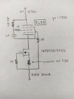
I am investigating using a EL83 pentode as a CCS in a parafeed output headphone amplifier I am designing, since the CCS will need to dissipate 6-7W. I have learned a weakness of the pentode CCS is the g2 dropping resistor cause a shunt, giving the CCS an impedance approximately equal to the dropping resistor, paralleled to the pentode.
In the case of the EL83, dropping resistor is ~79K whereas internal resistance of the EL83 is ~270K in my drafts.
Using a MOSFET as the lower device, I have gathered this will prevent current fluctuations associated with using the pentode alone. Are there other advantages of a hybrid setup over the EL83 by itself? This design is new to me, very limited information from what I have been able to find, trying to piece it together.
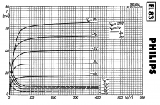
My proposed design is below along with the g2 = 170V EL83 curves. I have penciled in the IXYS IXTP08N50D2 depletion mode MOSFET as the lower device.
https://www.mouser.com/datasheet/2/...te_MOSFETs_N-Channel_Depletion_Mo-1623348.pdf


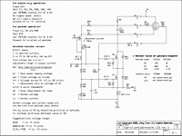
Thanks, Tim, was perusing his site on the "wayback machine" earlier today, going to have a second look, some interesting schematics there, maybe I will learn something.
