Not a pentode LTP but how about using a cascode LTP like L B hedge - The Wireless World Archive about half way down the page. Morgan Jones used something similar in his Crystal Palace amp, see Valve amplifiers M Jones. You could also parallel two triodes or use a choke instead of a resistor as anode load.
Andy.
Andy.
Last edited:
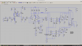
There is a quite a number of ways of stringing an amp together - a lot more than I first thought. Most have been discovered before I was born and then rediscovered in diyaudio! Is it interesting how the designers struggled with the limitations of the day. My brief is to try and replace the driver stages with a valve design as I feel using modern day op-amps is a bit of a cheat. However it is proving quite difficult.
In terms of the LTP cascode it needs more heater current and maybe elevated heaters than two high gain pentodes.
In terms of the LTP cascode it needs more heater current and maybe elevated heaters than two high gain pentodes.
I feel using modern day op-amps is a bit of a cheat" If the original designers of many valve amps had opamps, I'm sure they would have used them. One criticism is that they effect the tone of an amplifier, but really the OP stage and OPT has more influence on the final sound. The voltage amplifier bit, less so, I reckon, within reason that is.
"However it is proving quite difficult." It should be fun too. The problem is relatively simple, times the OP valve bias voltage by two, and add a bit on for NFB, that and make sure your driver has a bit of oomph to drive the inter-elcetrode capacitance of the OP valves.
I find knocking circuits up on the bench easier than wading through theory and doing lots of calculations, but everyone has there own approach I guess. Hands on fabrication relieves the old brain cells and gives you something to grasp. Often when asking advise, you get so much it's easy to get bogged down. Just have a go, knock something up, then have another think.
Good point about elevated heaters, it only takes two (or four if the tfmr has no center tap) resistors and a cap and a few bits of wire.
Andy.
Interestingly in the Radford STA series the phase splitter was the biggest source of distortion due to matching between triode and pentode. The radford revival models added a trimpot to balance the LTP. Now this is all relative as Radford used levels of GNFB that would horrify some senstive souls these days 🙂
You are right I could knock the driver circuit up on the bench rather than LT spice. I know the ultra linear output stage works very well as that is what is in the current design and have a reasonably accurate spice model of the o/p transformer for N/F.
Maybe we should score diyaudio amps for originality. Maybe deducting points for modern day semiconductors - say diode -1/2, mosfet/transistor -2, opamp -10.
Maybe we should score diyaudio amps for originality. Maybe deducting points for modern day semiconductors - say diode -1/2, mosfet/transistor -2, opamp -10.
Led = diode -1/2. Maybe the points need to be adjusted depending on whether the component is in the signal path or not. So if your LED is for illumination only... I count a CCS as in signal path.
SYclotron Audio | The Red Light District: A 15W Push-Pull Amplifier 84 LEDs in a push pull stereo amp. 😀
For a differential stage, the common'd screen grid source likely works fine. More constant V from an RC filter.
After some simulation in the LTP with dissimilar valves (6CB6/6EJ7), (EF86/6EJ7) it seems better to supply the screens separately just from a dropper resistor from the HT and a cap to ground + small grid stopper. This gives better AC balance. I guess the dropper resistor gives more similar AC current into the each screen and its this in-balance that appears on the plates.

I find knocking circuits up on the bench easier than wading through theory and doing lots of calculations, but everyone has there own approach I guess. Hands on fabrication relieves the old brain cells and gives you something to grasp. Often when asking advise, you get so much it's easy to get bogged down. Just have a go, knock something up, then have another think.
Yep on advise I will prototype the input and driver - I can load the outputs.
Attachments
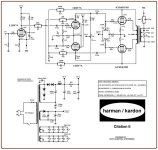
Why not try 12by7, video output, as Harman Kardon .Yep on advise I will prototype the input and driver - I can load the outputs.
Attachments
You can get 6197 tubes for about 1/10 the price of 12BY7 tubes. Very similar curves and ratings. (related to 6CL6)
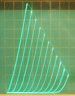
Then there is 12HL7 which is pin compatible with 12BY7, but twice the gm. Also cheap. Below, curve tracer selected 12HL7 tube in triode mode. Who needs 300B?
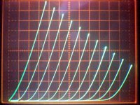
And if you don't like the Compactron 6BN11 etc (dual pentodes), there is an octal dual pentode with fabulous triode curves. 2nd pic
Then there is 12HL7 which is pin compatible with 12BY7, but twice the gm. Also cheap. Below, curve tracer selected 12HL7 tube in triode mode. Who needs 300B?
And if you don't like the Compactron 6BN11 etc (dual pentodes), there is an octal dual pentode with fabulous triode curves. 2nd pic
Attachments
Last edited:
Thought of another valve you could use - QQV03-10, two beam tetrodes on one bottle, 5w each side.
A.
A.
The 12BY7 is just a little low on gm. Does anybody have a spice model of the 12HL7. There actually a lot of choice.
Ordered some 6EJ7 to see how much spread in tolerance there is. Not something that gets put on the datasheets.
Ordered some 6EJ7 to see how much spread in tolerance there is. Not something that gets put on the datasheets.
That config worked for me - mu is 7.5 so a +/-16V swing on the grids maps to 240V on the anodes. Opamp supply +/-18V to maximize swing. Trimmer on the opamp side to set the anode current balance. I never populated the feedback resistors.Thought of another valve you could use - QQV03-10, two beam tetrodes on one bottle, 5w each side.
A.
6939 could be a good candidate.....
All of the published data is for use as a class C RF amp at relatively high plate currents (25mA). The curves get pretty crowded near the bottom where it would likely be used for an LTP driver. That 10K+ Gm will also drop off at low current. It may work, but testing is needed.
If you really want a one bottle LTP, use a 6J11. It is 2 X 6EW6 which are known to work great in Pete's big red board driving a pair of sweep tubes.
The 6AR11 is a pair of 6GM6's in one bottle. I have not tried them, but other remote pentodes work fine in LTP since the even order harmonics cancel.
Thanks, the tetrodes I am wary of as the plate resistance can become negative below 50v. The 5W pentodes tend to have lower gm. I am happy with 2W plate dissipation and high gain. The screens can be connected together however supplying them separately through HT resistors gives better AC match when the valve halves are mismatched. The best results seems to be from the 9-pin 6EJ7 or the 12-pin 6BN11.
- Home
- Amplifiers
- Tubes / Valves
- Pentode long tailed pair