No typo this time Dissi.
This is my 1st try at a 2.5-way using PCD, so it is possible that I've done something wrong. I'll double check all my files, etc. tomorrow.
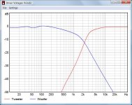
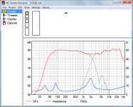
Although the summed response isn't perfect, it is flat +/-3dB. Below are my transfer functions and speaker impedance. They're not showing the same thing as what you mention although minimum impedance is definitely a little lower than his current version.
This is my 1st try at a 2.5-way using PCD, so it is possible that I've done something wrong. I'll double check all my files, etc. tomorrow.
Although the summed response isn't perfect, it is flat +/-3dB. Below are my transfer functions and speaker impedance. They're not showing the same thing as what you mention although minimum impedance is definitely a little lower than his current version.
Attachments
I was kind of hoping that given the quality of your build you might have some extra parts hanging around to try out. Those values look good. First graph below is with your values and the 2nd one is with the ones I posted yesterday, just for comparison purposes. The differences are minor.
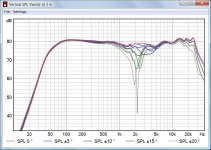
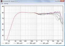
As usual, adjust the tweeter level to suit your ear but watch out now for that little peak at about 6-7kHz. That's right in the sibilance zone and the power response (ie off-axis responses) is equally as high right there too. Just to let you know, that is a product of the tweeter's diffraction with the cab's sharp edges. Moving the tweeter off center and/or rounding over the edges in some manner would help to flatten those peaks and dips out. If you don't use them yet either of these 2 programs will show you what I'm talking about.
jbagby - if you have Excel
Tolvan Data - if you dont
I should probably double check my work but you may put that xo together faster than I can do it and your ears will tell you right away what's what. I've assumed that your amp will be happy with a 4ohm load which means that minima of 3ohm should be fine, but if it one minimum ends up closer to 2ohm like Dissi's sims show, you are going to want to watch out for that.
Nice work on your cabs by the way. They look good.
Attachments
vvinder,
My apologies. I have made a small error in the set-up for my sims. I had input 2 for the number of woofers but in the configuration for a 2.5-way in PCD, this means that the sim was actually for 3 woofers. I'll re-work it and see what I can come up for you.
Dissi,
Thanks you for helping me to take a closer look at my work. I appreciate it.
Ok, this is better. See graphs below.
Tweeter
C = 12uF
L = .16mH (.3ohm)
R (before the xo) = 1.75ohm
R (after the xo) = 1.5ohm
Top and Bottom Woofer (before both of them)
L = 1.5mH (.5ohm)
C = 22uF (+ .75ohm shunt resistor)
Bottom Woofer (after the 1st one)
L = 1mH (.38ohm)
This time I'm finding it a bit harder to make 12uF and .18mH work well together for the tweeter. That's pushing the response up higher (in SPL) between 2 - 3kHz. But C = 11uF and L = .18mH with .5ohm total resistance in that parallel leg also works well. And 2.2mH is definitely too high for the 2nd woofer. Smaller here is better this time.
Let me know if you need a schematic or if you want to see what other specific values will result in. Again, sorry about my first mistake.
Cheers
Attachments
Hi again! I'v now tested the first filterversion, i could emidietly tell there is way too mutch energy in 1500-2000hz region, overwelming harshness. Maybe my ears are sensitive in that area. i'v previously never got settled with tweeter crossed under 3000hz. Now, iv applied a .8 mh coil to both woofers, and 33 uf as u figured out, after that a , 2,2mh to bottom wooofer. The tweeter got a 3.9uf instead of 12uf with .18 coil + 1 ohm at the end. This setup sound better, but how it shows on paper is propably crazy.
JReave, i dont possess a 1.5mh coil unfortunatly, i have a second 1mh and a 0.55mh, but in series it would be 1,3 ohm :-/
JReave, i dont possess a 1.5mh coil unfortunatly, i have a second 1mh and a 0.55mh, but in series it would be 1,3 ohm :-/
Last edited:
Hi,
Those graphs don't look very 2.5 way to me.
I can't see how the blue transfer function and
blue driver response add up in any practical sense.
I've never seen a 2.5 way where the 0.5 way
inductor is smaller than the main x/o inductor.
I suspect something wrong in your procedures.
I'd design it as a standard 2.5 way first. Coil
on the bass only, x/o on the bass mid, x/o
and attenuation on the tweeter. Then tweak
it by moving the bass mid x/o to both drivers.
The coil on the bass should mean it only needs
tweaking slightly to suit the new position where
it will roll off the top end of the bass unit better.
rgds, sreten.
Hi again! I'v now tested the first filterversion, i could emidietly tell there is way too mutch energy in 1500-2000hz region, overwelming harshness. Maybe my ears are sensitive in that area. i'v previously never got settled with tweeter crossed under 3000hz. Now, iv applied a .8 mh coil to both woofers, and 33 uf as u figured out, after that a , 2,2mh to bottom wooofer. The tweeter got a 3.9uf instead of 12uf with .18 coil + 1 ohm at the end. This setup sound better, but how it shows on paper is propably crazy.
JReave, i dont possess a 1.5mh coil unfortunatly, i have a second 1mh and a 0.55mh, but in series it would be 1,3 ohm :-/
Yes, no question - I screwed up on the 1st one I posted. A little embarrassing.

I don't know all your exact resistor values for the above parts, so below is just a close approximation of what you just put together looks like. It should sound better than what I posted 1st though, as it doesn't have too much energy in the HF. But it has the opposite result: too little.
The summed response of the new version I came up with looks fairly good, but I'm going to heed sreten's advice and take another look at it. Give me another day or 2 to see what I can come up with.
Attachments
I've never seen a 2.5 way where the 0.5 way
inductor is smaller than the main x/o inductor.
That's very helpful. Thanks. I think I see now that I still have too much of the lower woofer contributing to the output. The summed response may look fairly good but may be able to be improved upon. I shall give it another go or 2.
Cheers
jReave: "a close approximation of what you just put together looks like." Yes, thats how they sound, too mutch 1000hz, sounds like a icecream box with dimmed low higths.
I have a set of B&W 683, and they sound very good. But their frequency plot is far from neutral, but that is the sound im comfortable with. Here is a measurement test:
B&W 683 Surround Speaker System Measurements | Sound & Vision
I have a set of B&W 683, and they sound very good. But their frequency plot is far from neutral, but that is the sound im comfortable with. Here is a measurement test:
B&W 683 Surround Speaker System Measurements | Sound & Vision
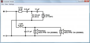
If you like a dip at 2kHz then the attached crossover could be worth a try.
I have abandoned the 2.5 way idea completely, it's just a huge effort and little return. Adjust woofer coil between 0.8 and 1 mH and woofer capacitor between 22 and 33 uF according to your taste.
I have abandoned the 2.5 way idea completely, it's just a huge effort and little return. Adjust woofer coil between 0.8 and 1 mH and woofer capacitor between 22 and 33 uF according to your taste.
Attachments
Just a thought, Dissi. But why go for such a low 2.2kHz crossover, beyond the way diyaudio people always seem to think it's SO clever. It's not.
No 5" driver has any struggles up to 3kHz. I like Troels' 3kHz crossover.
Peerless HDS PPB 830860
And adapting that to a D'appolito MTM design, or MMT here since we're stuck with it, you'd end up with something not dissimilar to this, say 1mH and 12-15uF on the bass and smaller caps on the treble:
Vifa PL14WJ-
You have to lose the LCR notch on the bass, since it takes impedance too low. You're have the modelling set up, so I'd be interested if it works.
jReave: "a close approximation of what you just put together looks like." Yes, thats how they sound, too mutch 1000hz, sounds like a icecream box with dimmed low higths.
I have a set of B&W 683, and they sound very good. But their frequency plot is far from neutral, but that is the sound im comfortable with. Here is a measurement test:
B&W 683 Surround Speaker System Measurements | Sound & Vision
Whenever you listen to anything or become accustomed to X, give your ears (and brain) a break. Once you stop listening to the yuck and hear the new your ears regroup and that becomes your reference. Just like when voicing a speaker, you don't simply say Oh thats good and ship it out the door with a single go around listening test. You make a small change and listen, day or two later you make another small change. This can take weeks to do. BTW that peak @ 4-5k is smack at the most sensitive part of the hearing range and will throw the sound of most music well off canter. Just looking at the response curve can tell you I would walk away in disgust, like I do when walking through BB, CC or any of the big box stores. They want how much for that garbage?! Yeesh
Just a thought, Dissi. But why go for such a low 2.2kHz crossover, beyond the way diyaudio people always seem to think it's SO clever. It's not.
No 5" driver has any struggles up to 3kHz. I like Troels' 3kHz crossover.
Peerless HDS PPB 830860
I don't know why so low either (it's not a 6.5"), 2.7-3k would be more like it. So yeah, 3k is a good ballpark figure to start with.
But why go for such a low 2.2kHz crossover
Simple answer: two 5" drivers are equivalent to a single 7" driver. Further, the driver has hidden break up issues at 5 and 9 kHz. The tweeter filter is 3rd order and 15 dB down at 2 kHz, that's very reasonable and, for comparison, more than in jReave's latest crossover.
Sometimes it's really funny here in the forum. A 2.5-way crossed at 2 kHz is no issue, but a 2-way crossed at 2.2 kHz is.

http://www.diyaudio.com/forums/multi-way/249036-troels-peerless-830860-vifa-xt25-dx25.html
Last edited:
Dissi,
I get slightly different results when I use your values. I'm wondering what you used as the FR for the Peerless woofer? It looks to be slightly different than the Peerless' graph which is what I used. Did you find a measured response somewhere?
I get slightly different results when I use your values. I'm wondering what you used as the FR for the Peerless woofer? It looks to be slightly different than the Peerless' graph which is what I used. Did you find a measured response somewhere?
Attachments
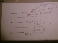
Dissi, i will try out your crossover later earlier today i tested this one, as you can see on picture, disconnecting the bottom woofer. I got this crossover from a monitor i built in the past, and it sounds clear as chrystal. My monitors have seas ER15 RLY and 27TFF... The only problem is how to get the bottom woofer to play along. The 6,8mh/33uf solution makes boombox bass, atleast in the room the speakers is now, ill move them down to livingroom and see... and add longer port tubes.
earlier today i tested this one, as you can see on picture, disconnecting the bottom woofer. I got this crossover from a monitor i built in the past, and it sounds clear as chrystal. My monitors have seas ER15 RLY and 27TFF... The only problem is how to get the bottom woofer to play along. The 6,8mh/33uf solution makes boombox bass, atleast in the room the speakers is now, ill move them down to livingroom and see... and add longer port tubes.Attachments
I'm wondering what you used as the FR for the Peerless woofer?
You are right, I used a measurement published in the german loudspeaker magazine KLANG+TON, but that's only a minor difference and does not really explain, why you get a rising frequency response towards 1 kHz and I get a falling one.
It's evident to me that simulation programs differ in calculation of bass reflex and edge diffraction. For example, my program is very much in accordance with the vented box simulations of WinISD, but quite different from some results of BassBox Pro I have seen. The calculation of edge diffraction is even more uncertain, because there is no known exact solution. The programs simply use various approximation methods which are more or less accurate. I hope that explains, why you can't expect two different simulations to yield identical results.
Much simpler than SPL is the calculation of impedance and filter transfer functions, and the results therefore should be quite close. But a comparison of the actual woofer filter transfer functions reveals a difference of more than 1 dB at 1 kHz, and that's too much IMO. This difference is not new to me, as I have encountered similar deviations of PCD a few times in the past. As a verification of my program showed a full agreement with Boxsim, I assume a little bug in some versions of PCD, but I don't know.
I don't at all say my program is better. I even honestly admit the simulated SPL in the range of 700 Hz - 2 kHz is often 1-2 dB lower than measured. On the other hand, your simulation always seems to have the microphone on axis of each driver, which neglects actual driver spacing. Nobody is perfect.
- Status
- This old topic is closed. If you want to reopen this topic, contact a moderator using the "Report Post" button.
- Home
- Loudspeakers
- Multi-Way
- peerless & seas 2-way