Hi all
Apologies if this is answered in another thread, I have searched but I cant find what I am looking for
I am planning a pcb for the Rogic buffer and have to make a decision on component purchase. I've sourced the Jfets etc, but I am unsure what to use for the 1uf capacitor,
Most will be familiar with this circuit.
I have in the parts box 30 of 1uf 250v philips MKT type caps, but I not so sure that these are the best. I have also looked at various 63v MKT, MKS
Resistor wise I am guessing that 1/4w carbons will be fine, although I have metal films in the right values.
I plan to use box type precision trimmers in the R2 position
I have bought the sk170bl, J310 and Irf530 in bulks of 50, And was planning on ordering the same number of PCB. I need 4 for my current amp, 12 for my next project and a few no doubt to ruin.
I may be able to post off spare boards to others if this is not a problem for Pedja. Not a profit thing obviously.
In a future project I plan an active filter. I am sure that i have read somewhere that a discrete buffer can be used instead of an opamp, is this the case? Linkwitz reilly is whats on my drawing board.
Regards
Blair
Thanks in advance
Apologies if this is answered in another thread, I have searched but I cant find what I am looking for
I am planning a pcb for the Rogic buffer and have to make a decision on component purchase. I've sourced the Jfets etc, but I am unsure what to use for the 1uf capacitor,
An externally hosted image should be here but it was not working when we last tested it.
Most will be familiar with this circuit.
I have in the parts box 30 of 1uf 250v philips MKT type caps, but I not so sure that these are the best. I have also looked at various 63v MKT, MKS
Resistor wise I am guessing that 1/4w carbons will be fine, although I have metal films in the right values.
I plan to use box type precision trimmers in the R2 position
I have bought the sk170bl, J310 and Irf530 in bulks of 50, And was planning on ordering the same number of PCB. I need 4 for my current amp, 12 for my next project and a few no doubt to ruin.
I may be able to post off spare boards to others if this is not a problem for Pedja. Not a profit thing obviously.
In a future project I plan an active filter. I am sure that i have read somewhere that a discrete buffer can be used instead of an opamp, is this the case? Linkwitz reilly is whats on my drawing board.
Regards
Blair
Thanks in advance
Hello,
Pedja might answer your questions in person here: http://www.diyhifi.org/forums/ Just register there and make sure to read the forum rules (no group buys...and that sort of thing 😀) He also has a website...you need to do a search.
About making a batch of 50 pcb using the exact number of devices... I think you need more FETs and MOSFETs because some matching is required.
Good luck!
I have even bult it with a 1uf film cap that comes in those little yellow boxes... nice high voltage unit... cheap as chips... still sounded wonderfull in there...
http://www.diyaudio.com/forums/showthread.php?s=&threadid=95007&highlight=
http://www.diyaudio.com/forums/showthread.php?s=&threadid=95007&highlight=
And was planning on ordering the same number of PCB. I need 4 for my current amp, 12 for my next project and a few no doubt to ruin.
Why so many? You only need one pair of buffers per amp!
I would use a polyprop for the 1uF cap and after you have set the correct voltage for J2, replace the (multiturn) trimmer with a resistor.
Yes you can build an active crossover using discrete buffers instead of opamps. But I would say that using this design for each stage of a crossover though is a bit OTT! You can find a much simpler version used in the active crossovers shown here . 😉
Nuuk said:
Why so many? You only need one pair of buffers per amp!
I have mission 753 speakers, there are 5 drivers per speaker. I thought it would be overkill fun to build up to a power amp per driver. So thats 1 buffer per amp.
My current amp has four power sections in it. Feeding the biamp speaker terminals on the missions. I would use this to test the buffer design.
Nuuk said:I would use a polyprop for the 1uF cap and after you have set the correct voltage for J2, replace the (multiturn) trimmer with a resistor.
Can you suggest a part number so that I can find similar? Are there any small ones that are good?
Nuuk said:Yes you can build an active crossover using discrete buffers instead of opamps. But I would say that using this design for each stage of a crossover though is a bit OTT!
There comes an economy of scale when building lots of the buffers, It seems a shame to go for op amps in the crossover if it is not too expensive to use discrete..
@Nordic. I will post a piccie of what I have. see if its similar to what you used.
I aim to factor a couple of cap choices into the buffer.
I have mission 753 speakers, there are 5 drivers per speaker. I thought it would be overkill fun to build up to a power amp per driver. So thats 1 buffer per amp.
Yes, an amp per driver, but you can drive them all from the same buffer!
My current amp has four power sections in it. Feeding the biamp speaker terminals on the missions.
Yes,mine too but with just the single buffer feeding both.
Can you suggest a part number so that I can find similar? Are there any small ones that are good?
Farnell order code 1215552.
There comes an economy of scale when building lots of the buffers, It seems a shame to go for op amps in the crossover if it is not too expensive to use discrete..
I agree but what I am saying is there are simpler buffer stages than this one. 😉
Hi NUUK
I am honoured you remembered me.
I got caught up in a measurement mic project which I will be completing the casework for this week, and a new dog who has been taking up some time.
However I just recieved a large order from Rapid where I sourced IRF510's from so I now have the parts to build the buffer.
I still have to source the caps. I have numerous 1uf polyester caps in my parts bins but only 4u7 polyprops. The X2 types.
My plan in my design though is to allow for various cap sizes so that I can try it out with polyesters but change over to something more exotic for my final amp.
I was reading this thread just a couple of nights ago. One comment that I do wonder about is the need for matching mosfets. I found instructions on matching transistors from the same batch ie 2sk170's but I am unsure how that applies to the buffers design as there is only 1 of each type in the design.
R!sk
Nice looking pcb. I notice you have a discrete power regulator on that, I recognise parts of its design from somewhere. Did you design it yourself, it looks similar to the one on pedjas site, but not all of the components are the same.
I was thinking along the lines of putting a discrete reg on my pcb. I think pedja mentioned using a fixed value regulator ic do step down. Pedja was using one after his discrete design so was not undully worried about ripple rejection. Designing in a discrete suppply would give flexability.
Actually Blair, I was thinking of building another Pedja buffer myself, hence my interest in your progress.
Pedja uses something like an LM7815 on his buffer because it is so compact and can go right next to the buffer circuit. I may try that myself this time.
I was also wondering if you wanted to sell a pair each of the J310, sk170bl, and Irf530 to save me from minimum order costs etc. I am starting to pull apart some of my earlier creations and will have a nice pair of Evox SMR 1.0uF polyprop caps I could offer you. 😉
Nuuk said:Actually Blair, I was thinking of building another Pedja buffer myself, hence my interest in your progress.
Pedja uses something like an LM7815 on his buffer because it is so compact and can go right next to the buffer circuit. I may try that myself this time.
I was also wondering if you wanted to sell a pair each of the J310, sk170bl, and Irf530 to save me from minimum order costs etc. I am starting to pull apart some of my earlier creations and will have a nice pair of Evox SMR 1.0uF polyprop caps I could offer you. 😉
I would be delighted to help out with the silicon, I would rather trade than sell.
If you are interested I could do with some impetus to get these boards designed and made, so if you could hold off and lend your input to some design work, I could put in an order for boards for both of us.
Blair
Sounds good. When you say boards, is this just for the buffer, or for the (GC) regulator circuit as well?
I could do a board with a reg on it. What I dont want to do price wise is seperate boards. On a small run, the setup costs far outstrip the board costs, so adding a reg circuit makes minimal difference to the final price.
It would be easy enough to give it dual function.
What I will do is make a first sketch tonight if the gf hasn't made other plans for me.
On the question of component matching. Should I be matching transistors?
**Edit** Do you mean the discrete regulator for the Gainclone itself?
I was thinking about making a board seperately for a lm3886 with the reg circuit and a relay based mute function.
My end goal with this project is to control the mutes for the lm3886 with a PIC to produce delays to the amp sections (power up thump) and possibly seperate digital pots after each filter section to be used as a crude 3 band equaliser.
I want the project to be fairly modular so that i can add start small and add extra functions as time goes by.
Yes, I'm not sure if you are still planning to have many of these buffers, but it will still be comparitively expensive compared to making up these relatively simple circuits on strip-board.
Unless you plan the whole thing, ie buffer. regulator, GC, out very carefully, it is, IMHO best to keep them spearate so that you get get the best physical arrangement when you actually start putting it all together.
In my case, because I am using a four-channel GC, I am having to look very carefully at where the buffer and regulator boards go in relative to the GC chips (hard-wired). At present, I am planning on the two chips on the heat-sink in the middle of the case, with the regulator circuit on one side of the heat-sink, and the buffer circuit on the other side, with the large DC blocker acting as the 'link'.
I used to match transistors but didn't with the Pedja buffer. It sounds so good, I'm not sure if I would bother next time TBH. 😉
Nuuk said:Yes, I'm not sure if you are still planning to have many of these buffers, but it will still be comparitively expensive compared to making up these relatively simple circuits on strip-board.
I work it out I will need 8 for my 10 channel amp. And I am going to use the existing 4 channel amp to do power my old mission 760i's in the bedroom. These will be my test bed for the active filter design, converting them to biamps. so there goes another 6 buffers.
The strip board option is still available to me, but I think I can get a much neater buffer by using a printed PCB. Pricing things out at Futurlec, the setup costs start at £12 or £24 with soldermask. The costs dont change much in comparison for doing multiplle boards so I will have buffers for this and many other projects.
Nuuk said:Unless you plan the whole thing, ie buffer. regulator, GC, out very carefully, it is, IMHO best to keep them spearate so that you get get the best physical arrangement when you actually start putting it all together.
Agreed. And I will probably end up doing a fair amount on stripboard as well in the finished amp.
Nuuk said:I used to match transistors but didn't with the Pedja buffer. It sounds so good, I'm not sure if I would bother next time TBH. 😉
I take it I would only be matching per stereo channel if I were to put the effort in.. ie not matching a J310 to a SK170BL to a IRF510?
I take it I would only be matching per stereo channel if I were to put the effort in.. ie not matching a J310 to a SK170BL to a IRF510?
Yes, that's correct, and matching all the channels in your multi-amp projects! Full-range driver anybody? 😀
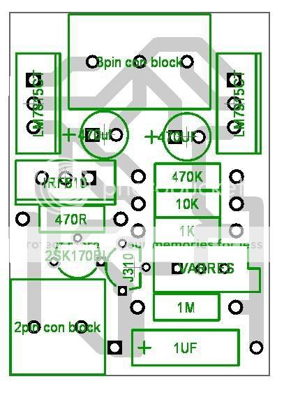
My starter for 10 on this design was another thread on this forum where Pedja Himself made some pcb design suggestions. So I am not going to claim any credit for anything here.
This is a crude first design for the buffer and uses lm7815/7915 voltage regs to drop the voltage down.
I have to make a bit more space on the pcb for cap choices
I think its best to stick to single sided use
Comments are welcome, especially if there are any mistakes in there. I will go through and check datasheets etc to double check pin configs
Hi,
caps become the biggest space/pin pitch problem when you start experimenting.
Try to make sure every capacitor location has at least two (useful) pin pitch options and leave adequate space for physically large caps. PP are always bigger than PES/PET.
I would prefer to see 0.1inch pitch connectors alongside/under the 0.2inch pitch terminals you have shown. Then you have a choice of how you make the on/off board terminations.
What do the regs need for caps around the pins?
- Status
- Not open for further replies.
- Home
- Amplifiers
- Chip Amps
- Pedja Rogic Buffer and component choice for PCB design