Nordic said:Be a good boy and rotate that J310, the same way as the other transistor... 😀 the couple of mm extra traces won't hurt anything, I promise. But it will look prettier.
LOL. My bubble is popped! I did not realise that aesthetics had an effect on sound quality
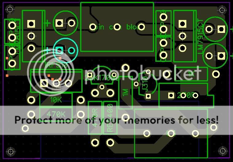
On the subject of placements, is this going to be a bit too congested?
but if all the polarised caps and all the semiconductors are oriented in the same directions, then there's less chance of a misplaced component screwing up the circuits performance.justblair said:
LOL. My bubble is popped! I did not realise that aesthetics had an effect on sound quality
On the subject of placements, is this going to be a bit too congested?
I was like that too... working with Carlos drove me to the oposite side of the street...
I have tried a few things with "optimal" layout (schematic wise) and then the same circuit with some irregularly long traces to get simetric layout... and only in one case did I notice any influence... and there I suspect a soldering error... as it was a big 200 hole board.
Andrew also made a valid point...
Nordic said:I was like that too... working with Carlos drove me to the oposite side of the street...
That has so many interpretations. 😀
AndrewT said:but if all the polarised caps and all the semiconductors are oriented in the same directions, then there's less chance of a misplaced component screwing up the circuits performance.
I take your point, though looking at the design, the effect of rotating the transistor not only leaves longer traces, but it also reduces the gaps between traces. I still intend to thicken up the traces a little to boot.
Perhaps its because I have developed the boards myself in the past that I am a little cautious about this. This time I am getting them printed, so tolerances should be smaller. I have moved into my GF's flat and one we have less space, so my drill press is still at my place and two, she was more than nervous the last time I developed in the kitchen here...
Nordic said:I was like that too... working with Carlos drove me to the oposite side of the street...
I have tried a few things with "optimal" layout (schematic wise) and then the same circuit with some irregularly long traces to get simetric layout... and only in one case did I notice any influence... and there I suspect a soldering error... as it was a big 200 hole board.
Andrew also made a valid point...
Both of your advice is valued and , and I think that if I were producing a more complex board (with more chances of errors) I would be more inclined to take heed. With less components to monitor though and a little care, I dont think this will be an issue (famous last words?)
I wonder though if comprimises are to be made on the track lengths it would be more appropriate to ease the congestion in the power supply area of the board to make it easier to construct. If I were printing myself I would not dream of placing components so close together as small errors in drill positioning could make things even tighter.
Anyone had bad experiances using printed boards and small component clearances? Am I being neurotic?

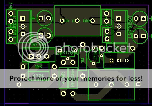
I have played around some more.
Taking on board recommendations about having components aligned to reduce mistakes in construction I have orientated the tank caps in their pairs. Thanks Andrew and Nordic for the tip here, I think it looks neater.
I tried out spinning the J310 90 degrees as per Nordics suggestion. However as well as making the track length slightly longer, it also reduced the seperation. Especially as I have widened all tracks to 2mm. Sorry Nordic, i just couldn't help feeling it was a compromise that I could not make.
Other changes:
- Changed connection to power ground plane to "direct" rather than spoked
- Reorganised the caps in the +ve side of the regulator
- Introduced a power plane to the +ve and -ve post reg rails to reduce resistance
- Made more space around the tab side of the regs, to avoid shorting with caps, and allow small clip on heatsinks if necessary
I would be very gratefull for further comment. I am about to do my final checks on the component sizes, hole sizes and DRC checks before sending off the design for manufacture.
Pedja has mentioned that producing a few of these boards for interested parties is acceptable, however as he now sells his designs commercially, this should be in limited numbers purely to reduce the cost per board.
Anyone interested please pm me, unless the numbers get out of hand, I should be able to make a few... This is not a group buy!!!
Hello,
You have made nice progress on the layout.
For a PM it would be convenient if your profile allows to do so.
Best, Arjen
vrhff04_at_xs4all.nl
You have made nice progress on the layout.
For a PM it would be convenient if your profile allows to do so.
Best, Arjen
vrhff04_at_xs4all.nl
Thought it did? Oh welll for others please email me
blairthompson_at_btinternet_dot_com Please enter DIYAUDIO into subject header...
Arjen... your mailbox will soon have a new entry...
blairthompson_at_btinternet_dot_com Please enter DIYAUDIO into subject header...
Arjen... your mailbox will soon have a new entry...
i already finishing gainclone 3886 n i wanna try install this buffer..
can i uses this buffer before my gainclone?
@justblair
btw can u post ur eagle files to me?
thx bro
can i uses this buffer before my gainclone?
@justblair
btw can u post ur eagle files to me?
thx bro
Hi
Yes it can, though be aware that the low pass filter stage is not included on this board.
I did this on Diptrace, not Eagle.
Mail me at the above address.
Yes it can, though be aware that the low pass filter stage is not included on this board.
I did this on Diptrace, not Eagle.
Mail me at the above address.
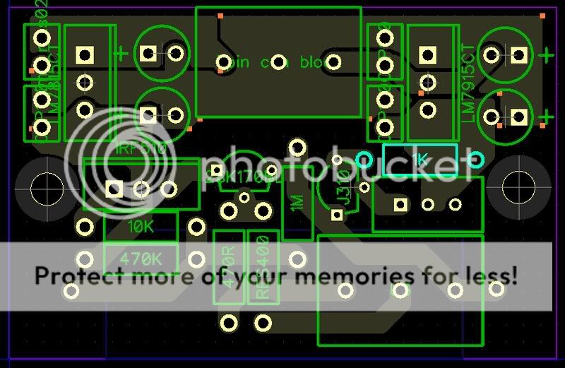
Been doing some checking tonight.
I found an error on the connection of the J310. I was a little unsure about the alignment to begin with. Got it wrong, Pedja pointed out my error, and despite this I still managed to get it wrong. I must have been tired when I read his suggested corrections.
However I have checked against the datasheet, and also against the diagram and stripboard layouts from decibel dungeon... Thanks Nick, I always seem to end up back there when I get stuck.
I am 95% certain that I have corrected the J310 properly this time, wouldn't mind a double check from someone.
Other than that I think that all is well. Though I am having a dilema about mounting holes.
I printed the design off for checking component sizes. Got a bit of a fright, I hadn't really visualised just how small this board is, about the size of a zippo lighter.
I have had a couple of other ideas that I may post
Thanks Nick...
Now the question is how important are mounting holes to people?
It means enlarging the board ever so slightly if I want to fit two M3 bolts and spacers.
I am also looking at the in and out for the signal. I am using a 3 way connector block at the moment. However I could go to a smaller molex style plug. It means using crimps, though it would be easy to solder signal wire right in.
Advantage to me design wise is I can probably drop in a Vishay MkP1839 bypass capacitor for the sonicap without increasing the signal paths substantially.
Thats the trouble with spending time looking at this. Keep wanting to tweak, 😉
I think some mounting holes are always a good idea. Otherwise it limits the options for fixing the board into the case.
I'm happy with a three-way terminal block but am not going to cry if it is changed. 😉
I'm happy with a three-way terminal block but am not going to cry if it is changed. 😉
Nuuk said:I think some mounting holes are always a good idea. Otherwise it limits the options for fixing the board into the case.
I'm happy with a three-way terminal block but am not going to cry if it is changed. 😉
Mounting holes for M3 size
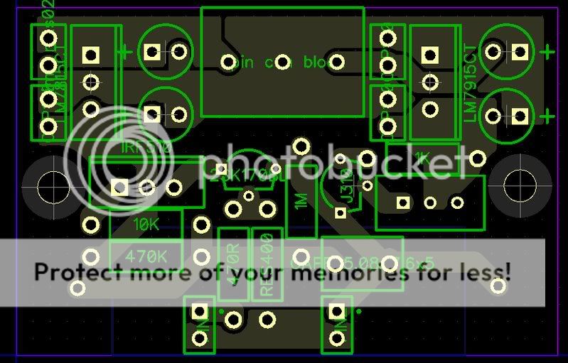
And a first go at using 2 0.1' headers instead of the 3 way terminal block. The new cap is a Vishay MKP1837 signal bypass as recommended by humblehomemadehifi and others.
"A gain in clarity and transparency making instruments better separable from each other, the violins in an orchestra are a group of individual violins instead of one mass. Jazz drum brushes sound more like a brush than a "shush".
Verdict: Can’t live without them! – Use them as bypass cap with any capacitor, they cost practically nothing!" Humblehomemadehifi, cap test
Just so happens I have a bundle of these in my parts bin 10nf size. Changing to smaller connectors frees up space for the bypass.
Still need to size up to make sure molex kk, gold plated headers will fit.
Just so happens I have a bundle of these in my parts bin 10nf size. Changing to smaller connectors frees up space for the bypass.
I'm confused! 😕 Isn't it a 1 uF you need for the buffer?
The buffer asks for 1uf and the 1uf still remains on the rear of the board.
However some report that using the 10nf bypass, small as it is improves the performance of the sonicap (and other) capacitor in terms of sonics.
I have to admit that I do not fully understand the choice of 1uf in the buffer by Pedja. The maths of the buffer is still a step to far for me... I am learning his stuff much slower than I would prefer.
My reckoning is though, that 0.01uf is within 1% of its overall value, and capacitors rarely achieve 1% tolerances, 5-20% is more usual. So adding it should be inconsequenal. i.e. the combined value of both capacitors although theoretically slightly higher than Pedja specced, is still within a reasonable tolerance.
I fear that i am about to be told that I am very wrong here , but I dont mind learning if I am mistaken...
My suspician is that the bypass may have little or no effect on the quality of sound. But as I have a small cache of them, it may be nice to be able to try it out. Others I have read believe they have detected an improvement.
I have both of the above designs saved, so if I am barking up the wrong tree, I can go with the origional design?
However some report that using the 10nf bypass, small as it is improves the performance of the sonicap (and other) capacitor in terms of sonics.
I have to admit that I do not fully understand the choice of 1uf in the buffer by Pedja. The maths of the buffer is still a step to far for me... I am learning his stuff much slower than I would prefer.
My reckoning is though, that 0.01uf is within 1% of its overall value, and capacitors rarely achieve 1% tolerances, 5-20% is more usual. So adding it should be inconsequenal. i.e. the combined value of both capacitors although theoretically slightly higher than Pedja specced, is still within a reasonable tolerance.
I fear that i am about to be told that I am very wrong here
, but I dont mind learning if I am mistaken...My suspician is that the bypass may have little or no effect on the quality of sound. But as I have a small cache of them, it may be nice to be able to try it out. Others I have read believe they have detected an improvement.
I have both of the above designs saved, so if I am barking up the wrong tree, I can go with the origional design?
I fear that i am about to be told that I am very wrong here , but I dont mind learning if I am mistaken...
Not by me! 😉
There is an argument that bypassing caps smears the sound but I never found it to do so. One of my first hi-fi mentors always recommended three or four caps instead of one. This simple active buffer being a typical example.
An externally hosted image should be here but it was not working when we last tested it.
You know Nick, I have looked at that diagram maybe a dozen times, and I never twigged that the caps were in parralell. I was too busy trying to work out how the filter section was working.
Is the new design OK with you then? I ont want to go completely off track, these designs have a habit if kinda expanding.
I was reading up on lm317's for an hour or more last night and almost convinced myself that it would be worth changing the regulator stage. Had to keep reminding myself that this would be the second set of regulators in my design. Hence the relative simplicity.
- Status
- Not open for further replies.
- Home
- Amplifiers
- Chip Amps
- Pedja Rogic Buffer and component choice for PCB design