peculiar Fisher circuit
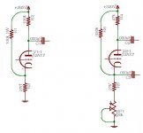
I have attached an image of a post tone control gain stage and the phase inverter for a Fisher X-101-B. I was curious what the purpose of R1 and R6 are.
It seems like they would reduce degenerative feedback (by a controllable amount) in the gain stage across all frequencies equally, which would be an advantage over bypassing with a cap I guess. Its less efficient on the power, though.
Why would you do this in a cathodyne?
Anyone else ever see this before?
Think nothing of that. Happens to all of us at one time or another.
Those resistors will shift the operating point of the valve. They will raise the voltage at the cathode making for greater reverse bias. I've seen this setup used in some circuits that have lower than optimum B+. I, too, would be interested in what other effects this might have on the operation of those stages.
I have a Harman Kardon and a Motorola amplifier that both use a similar configuration.
Wade
Well, in this amp there is more than adequate B+ for 12ax7s. Why not just use a more optimal Rk? I'm thinking they were looking for less cathode degeneration here.
The cathodyne stage is what's got me here. It seems like they just made it more complex for no real reason. I can't think of a benefit for R6.
The cathodyne stage is what's got me here. It seems like they just made it more complex for no real reason. I can't think of a benefit for R6.
Besides increasing bias slightly, they also provide some ripple cancellation.
Maybe that was their reason for it.
They eliminated these resistors in the X-101-C.
Yeah, that's probably it. The cathodyne is notorious for its poor PSRR (a fact that seems to have concerned John Broskie quite a lot).
SpreadSpectrum said:The cathodyne stage is what's got me here. It seems like they just made it more complex for no real reason. I can't think of a benefit for R6.
Yeah, that is very strange. It looks like the designer didn't know that a cathodyne is inherently self balancing. Sure, they didn't have laser trimmed, precision, +/- 1% metal films back in "the day", but still, looks like way too much trim pot there for balancing the +/- 10% C-comp resistors used quite commonly then.
The most peculiar thing about it is that you have a current balance pot, but no current sense resistors anywhere. If you're fortunate enough to have the right tubes with the right heater voltages and currents, you can use them to substitute for cathode bias resistors: free DC for sensitive front end stages back when they didn't have silicon diodes.
For me R1 gives the right amout of -Vg with a small Rk = more gain without an elco.
As for R6,is the cathodyne DC-coupled to the previous stage? If it is the case,like that you raise the anodevoltage giving the pre more space.
Mona
As for R6,is the cathodyne DC-coupled to the previous stage? If it is the case,like that you raise the anodevoltage giving the pre more space.
Mona
Also, the large 30k pot might have been used to reduce cost. Although not strictly necessary to have that large a range to balance the cathodyne, there are sometimes economical reasons to select components and not strictly technical.
Dunno if the 30k pot was used elsewhere, but it's likely it was a standard part used in the Fischer line. Remember, these companies were trying to make a profit, and saving even a few pennies by doubling up on components (i.e. - using a single component type instead of multiple unique components) was (and still is) common in the industry.
Finally, high-end manufacturers like Fischer had the luxury of selecting tubes and controlling sources. Unlike us, the large companies had the clout and resources to specify exact performance from their components - hence, if it's a circuit that depends on particular tube characteristics then that would not at all be unreasonable in a Fischer design but could be problematic in our DIY builds.
Wow... so far no one got it!
The two circuits have quite different purposes. The one on the right (with the 30K pot in the cathode, in series with a 27K resistor) is just a cheap trim pot suitable for a fairly wide adjustment of both the operating point and the phase-splitting balance. It would be instructive to see what's driving the grid of that right-hand snippet. I'm betting direct-connect to a signal path that has at least 100 VDC superimposed on it.
The one on the right - the purpose of the 100K B+ to cathode is to act as a ~2.8 milliamp current source (basically independent of signal), widening the range of cathode swing that the input signal will incur in the course of amplifying the signal. Again, it would be instructive to see what is leading TO the grid of this stage. I'm betting it isn't the very first stage, but a subsequent mild-amplication middle stage.
There you are.
GoatGuy
Wow... so far no one got it!
The two circuits have quite different purposes. The one on the right (with the 30K pot in the cathode, in series with a 27K resistor) is just a cheap trim pot suitable for a fairly wide adjustment of both the operating point and the phase-splitting balance. It would be instructive to see what's driving the grid of that right-hand snippet. I'm betting direct-connect to a signal path that has at least 100 VDC superimposed on it.
The one on the right - the purpose of the 100K B+ to cathode is to act as a ~2.8 milliamp current source (basically independent of signal), widening the range of cathode swing that the input signal will incur in the course of amplifying the signal. Again, it would be instructive to see what is leading TO the grid of this stage. I'm betting it isn't the very first stage, but a subsequent mild-amplication middle stage.
There you are.
GoatGuy
Well, now I guess we all know about it.
😀
Wow... so far no one got it!
The two circuits have quite different purposes. The one on the right (with the 30K pot in the cathode, in series with a 27K resistor) is just a cheap trim pot suitable for a fairly wide adjustment of both the operating point and the phase-splitting balance. It would be instructive to see what's driving the grid of that right-hand snippet. I'm betting direct-connect to a signal path that has at least 100 VDC superimposed on it.
The one on the right - the purpose of the 100K B+ to cathode is to act as a ~2.8 milliamp current source (basically independent of signal), widening the range of cathode swing that the input signal will incur in the course of amplifying the signal. Again, it would be instructive to see what is leading TO the grid of this stage. I'm betting it isn't the very first stage, but a subsequent mild-amplication middle stage.
There you are.
GoatGuy
I am afrait we are'nd there at all 😛
The balance of the splitter has to be adjusted so that the total resistance in the anode- an cathode-circuit is the same.The operating point is imposed by the voltage applied to the grid and comes from ??
The 330k takes some current from the cathode resistance leaving less for the tube and thereby raising the anodevoltage,giving more space for the tube.
As for the left picture,a smaler cathoderesistance doesn't widening the range.On the contrary the possebility of the cathode following the input is become smaler (needs more current).
Mona
Here's what is feeding the grids:
Left - Ground referenced signal.
Right - Direct-coupled signal from previous stage anode, 105V.
Left - Ground referenced signal.
Right - Direct-coupled signal from previous stage anode, 105V.
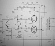
I've been working on a Fisher 500S, just want to share this peculiar bias circuit.
The X-101-B has the same bias circuit. It is a kind of hybrid fixed/cathode bias using the small signal tubes heaters as a cathode resistor. That way the phono and first stages can have a cheap DC supply.
- Status
- Not open for further replies.
- Home
- Amplifiers
- Tubes / Valves
- Peculiar Fisher circuit