Greetings all,
Got a peavey 1200 amp that is a pain in the **** anyone on the forum got any experience with them?😡
Got a peavey 1200 amp that is a pain in the **** anyone on the forum got any experience with them?😡
Lots of us have, perhaps if you told us what the problem was you were trying to solve...
And is that a PV1200 or a CS1200 or an XR1200?
And is that a PV1200 or a CS1200 or an XR1200?
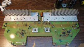
Thanks for the reply's . It's a PV1200 amp that had quite a catastrophic failure took out all the drivers and pre drivers as well as Q104/105, the op amps and the diode biasing string. I have replaced all the drivers and pre drivers with MJ15024/25 and Q104/105 with MJE340/350 as well as replacing all the op amps including the 3080. The only thing I could not get is the CR113/117 so I used 2 x 1N4007 in series. I compared the volt drop across the 1N4007 to a working module and it's within a few millivolts. I powered up the module using a 58-0-58 current limited psu and checked the voltage across R146 which reads 0v even on the millivolt scale. The be voltage across Q104 is 0.612v and Q105 is 0.601v. The total voltage drop across the diode string CR108,113,117 and110 is 2.9v.
When my PV-1.3k suffered a similar disaster, lots of little tan 50 v ceramic bypass caps were blown, also some of the green cylindrical 50v caps. Look for no DC voltage across them. I also had some burned driver card lands and a burned resistor or two on driver card. Look for resistor voltage drop higher than the wattage would allow. I had a lot of burned emitter resistors, I suppose you checked those? All the VI sense resistors were toast, too. They must have kept hooking up shorts to the amp repeatedly. The J174 was blown on one channel. All the zener regulator diodes were blown, and stuff back on the PowerSupply board.
The VI limiter transistors are supposed to be off, if that is Q104&105 are. .6 v is very nearly off.
You may have to monkey with the diode stack resistor to get decently low crossover distortion. MJE340/350 aren't I believe original, and Peavey sorts output transistors, you may not have done so as tightly. When they went from SA968B SC2238B predrivers to MJE15034/35 in the service bulletin for my amp, they changed the series resistor in the diode stack. I still can't measure any DC current silent on any of the emitter resistors, one reason the amp is still on the table. Doesn't sound bad but I haven't trusted it to put it on $$$ speakers and give a full distortion test. Just trash speakers so far. I don't know if idle bias current would go through one output transistor pair or all of them. I matched my OT's within .01 v Vce gain 10. I got from farnell - 0.13 and 0.12 Vce mostly, put a couple of 0.11 v parts in the bin. That's 12 v test voltage, 100 ohm base resistor, 10 ohm collector resistor, on a little TO3 heat sink.
Enzo said to look for no crossover distortion, I don't have a working scope or distortion meter either. I can build 6 amps for the cost of a working scope. Low cost used scopes need 100 e-caps or are new ****ese **** with a 60 v probe limit. My PV-1.3k was whanging to 170 vdc out until I found the bad solder joint on the feedback input of the first 4558 op amp.
Last edited:
When my PV-1.3k suffered a similar disaster, lots of little tan 50 v ceramic bypass caps were blown...........until I found the bad solder joint on the feedback input of the first 4558 op amp.
Wow. I'm surprised it's that bad when it blows.
Hi,
Yes also got my parts from Farnell. I did replace all the 0.22ohm emitter resistors as they where all o/c. Luckily I still have a working amp so I will compare voltages with that one that should give me some clues as to the fault.
Yes also got my parts from Farnell. I did replace all the 0.22ohm emitter resistors as they where all o/c. Luckily I still have a working amp so I will compare voltages with that one that should give me some clues as to the fault.
They got smarter from the PV-1.3k. Some of those resistors blown on your schematic saved more expensive hard to find parts. My zeners were blown making the op amp rail voltage, my 4560 was blown, my input op amp was blown and the hard to order 3380 transconductance amp was blown too. Making those resistors tiny gets you down to ordering from one distributor, possibly newark. I had to order 3380 from California to online order, and jameco split the order from their two warehouses, making two $12 freight bills instead of one. Enzo says how great Peavey parts supply is, but you have to call them on the phone, not internet order. I didn't even have free long distance telephone service when I bought these parts. I could just see myself standing next to a howling diesel refrigeration unit at the pay phone down the block, shouting part numbers into the handset and trying to hear the response.
Looking at the board, this jewel doesn't even have DDT does it? Saves you a 3380 and a J174 too, another part that isn't being stocked.
BTW MJE15031/32 are down to $1.40 each now they are making them in ****a, may as well buy a 300 v rated part for drivers and try to limit the damage going backwards the next time somebody pulls a speaker phone plug out part way. When I did this they were $4.
I'm building a rail disconnect using nfets to save output transistors, but because of the flying speaker return it is messy. Separate wall transformer power supply 5 vdc stuffed in the corner, about 35 parts, just for DC detect, disconnect, latch fault and drive indicator LED's.
Bottom line, use dual banana plugs or speakons, instead of 1/4 phone plugs.
Last edited:
I haven't checked everything component yet but you're right about the zeners and the opamps. Probably dead too.
What is disappointing is the damage. It's not just a couple of outputs and drivers. It's the entire module.
I doubt I'll be rebuilding it. Just not worth my time.
I'll probably reuse the chassis and the transformer and retrofit it with another amp.
Luckily the transformer is still good and I believe it has a center tap. Otherwise, it's a total loss.
Come to think of it, I don't recall the vintage QSC 1400, the ones with the collectors grounded, having such extensive damage when failed.
- Status
- Not open for further replies.
- Home
- Live Sound
- Instruments and Amps
- Peavey PV1200 amp