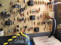
I'm after a sub for CS-800 driver board, op amp U4, 70487478? I have some op-amps that just might work! They are Tl072cn, OPA2134pa and RA3678 but I haven't tried them in case they displease the great smoke god Ha! Would one of these work by any chance? (its the one on the bottom of the photo)
Attachments
The suffix matters, the CS800b schematic I have has no op amps at all. The CS800s schematic won't tell you what U104 is,. but U101,102, U103 are 4560's same pinout as your TL072n. U104 is a 13080 which a part number from merged out Harris. It is a transconductance amplifier with a weird pinout, and weird characteristics that make it unique. For the DDT to work and keep the speaker coils from frying from distorted guitar sounds, You need one. A CA3080 from merged out RCA is probably the same thing, since it has the same pinout. I bought some from Jameco in Calif. I haven't really tested it to see if it works, I don't have a guitar or crunch pedals. The circuit works without it, all except for the DDT speaker protection. Enzo keeps saying how nice the Peavey parts dept is, but you do have to talk to them on the phone, they don't sell via the internet. The other unique parts I know of are the J174 jfet (just went 2000 minimum buy at newark.com) and the dual bias diode embedded in the heat sink. Output relays are unique, of course.
The 87478 is not just an op amp, it is an OTA. It is a CA3094.
Indianajo, he has a wind tunnel CS800, the last production version before the CS800X. You can use the CS800X schematic.
Also, RR is in Australia, so he won;t be calling Mississippi. But the Peavey distribution in that country may be able to provide the part. But we need to know for sure it is bad first.
RR - if you think your 87478 is bad, here are two options. First is to sub the one from the other channel. But really the second is to simply remove it. All that IC does is act as a compressor for the DDT circuit, it is not necesary for the basic amp function. If removing it restores lost function, then either it was defective itself (and subbing it will reveal that) or it is being triggered on by the rest of the circuit. I don't find them bad very often, but it does occur. DDT only does ANYTHING when you drive this amp to full output - it only comes on during clipping. If we are chasing a lack of function in the channel, we won;t be coming anywhere hear to clipping.
I'm getting +15.05vdc and -13.47vdc on all op-amps?The power board is outputing +15vdc and -15vdc. There is 19vAC on the fuses on the power board but zero on the cathode side of the in4003 diodes that Ive replaced with in4004? The power board resistors are very hot.It was (26v) working before but at 24vdc?
Last edited:
Check the schematic. The power supply board drags +/-15vDC off the main +/-74v rails through R98 and R100 with a couple zeners. But that supply is for the crossover socket only. The +/-15 for the chips on the channel are derived right on the channel boards. Those two resistors are 2k 5w and will get hot normally. They should have about 74v on one end and 15v on the other end.
The +26 is separate from them. DO you not get 26v now? 24 would be fine too, it isn;t regulated.
The +26 goes onto each power amp board and then over to the driver card. Look lower left corner of the amp board schematic and find the 7815 there. That makes the +15 for the op amps. Then -74 from the rail is dropped through R188 and R198 both 1k 5w, to make -15v regulated by Q129 Q130. SO if your +26 was really gone, you'd have no +15 on the boards.
You know, I don't know that being a volt low is such a big deal. The amp should still function.
The negative on the op-amps is 7.40vdc now? So I suppose its just a matter of putting in a new 15v regulator. What I cant figure out is why the 26v on the power board is zero volts and all 5 big resistors are really hot except of course the one on the 26v? It was working fine before but on 24v.The earth for the 26v that goes to TB1 has no continuity back to earth on power board 26v? Is it supposed to have continuity, I'm asking because the tab on the TB1 is loose?
Too late to edit out the regulator part. It looks like my problem is with the 26v then? Q29 & Q30 on the driver board are OK I replaced Q31 because it had had its day, with BC547, the sub for it was BC550 But BC547 has the same specs so I used that.
Last edited:
Well its back to square one with the power board,it can only mean that the transformer is intermittent so I'm binning it.Thanks for your help Enzo.
- Status
- Not open for further replies.
- Home
- Live Sound
- Instruments and Amps
- Peavey op-amp sub