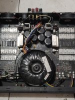
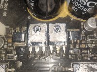
Good Day All. I have in front of me, a Peavey CS4000 that had a previous attempted repair but has no output. One parallel bank of 4 outputs were replaced with the original parts, but 2 gate resistors have been replaced with outboard mounted ones as the package size is unavailable locally. The amplifier turns on, but the only light that is on is the DDT light on both channels. It is making rail voltage, and there is no significant DC voltage on the output terminals. Can someone help me troubleshoot this amp and its DDT protection circuit. Thanks
Attachments
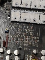
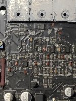

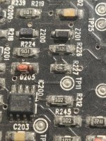
Finally getting back to this one. What is really needed is help troubleshooting the DDT protection circuit as the amp turns on and only the DDT light illuminates and the fans come on. R227 seems to be ok, just my pic wasn't clear and solder show signs of age... I believe the amp is fully powered up, but I will post some various reference voltages to confirm...
D109 -65.7 -66.0. -65.7
D110 66.2 65.9 66.2
Q131 66.0 131.5 65.9
Q132 -132 -65 -131.8
Q122-128 66.0 6.6mv 65.5
Q121-127 -65.8 -4.6mv -65.2
Q113-119 -65.5 -9.5mv -64.9
Q114-120 65.7 6.8mv 65.1
D109 -65.7 -66.0. -65.7
D110 66.2 65.9 66.2
Q131 66.0 131.5 65.9
Q132 -132 -65 -131.8
Q122-128 66.0 6.6mv 65.5
Q121-127 -65.8 -4.6mv -65.2
Q113-119 -65.5 -9.5mv -64.9
Q114-120 65.7 6.8mv 65.1
Attachments
We need a schematic,period.
Diagnosing from pictures in a complex device such as this one is impossible.
Doubly so in one which has been messed with; once you start breaking tracks "the circuit does change".
All I can tell you is that DDT compares input and output signals, generally at the input differential pair, and triggers when they become different.
OR, id amp has Op Amp input, it detects voltage out of it; a normal working amp shows little voltage there, a few mV ; a clipping one hows a couple Volt there, the "error correction signal" trying to correct output "error"(clipping)
In both cases error signal lights a LED but more important, trigger a compressor/limiter.
FWIW IOC means "Input Output Comparator" and does exactly that.
DDT means Distortion Detector Technique, exactly same thing, only one brand is used by Crown wh invented it, second by Peavey.
FWIW my own amplifiers use a DDT system, only mine is different and MUCH simpler, I used undocumented circuit behaviour to my advantage.
I have been trying to get a Service Manual for this amplifier, with no luck. If anyone can help in that department, it would be greatly appreciated.
If there is anyone with knowledge of the DDT circuitry, or even the input signal path, help would be also appreciated.
If there is anyone with knowledge of the DDT circuitry, or even the input signal path, help would be also appreciated.
I could be wrong, but I tend to think the DDT light is a symptom rather than a problem. Clear up whatever is wrong with the amplifier and the DDT light will go back to sleep on its own.
For schematic the best bet is to contact:
customerservice@peavey.com
For schematic the best bet is to contact:
customerservice@peavey.com
Yup, gotta have that schematic -- unless you want to have dozens of smart, helpful folks here spinning their tires in circles with 'helpful tips'. 😉
As fun and interesting as those voltages are, no useful diagnostic conclusions can result. Is it possible that you really do have 119 to 132V on each of those 6 transistors? (*1) What's the reference? I normally assume Ground, but that seems more than a little high, if so.
With news such as this, I'd suggest first confirming polarity (NPN/PNP), then measure Vbe. At that point the Emitter-Collector voltage becomes noteworthy. Without at least 2 significant digits of Vbe (impossible to discern in a 60 to 90V measurement), it's hard to make any assessment-of-reasonableness about the voltage on the Collector. What IS likely is that those voltages that are within ~10mV of Ground -- if they're part of the DDT circuit -- are NOT what is triggering the Protect Mode.
*1: Took me a couple extra looks to sort your table of values. Some of what I thought were voltages, seem to be in fact Component Designations -- or a range of them! If more than one device in a series of Component Designations have similar values, make a table! Put in the lines and everything, then post a JPEG or similar. Even with no schematic, a few reasoned conclusions could be drawn.
Schematic.
Best Regards
Does that mean something like 1 to 1½ cm lead lengths? A ferrite bead might be necessary. Gate trace inductance isn't something to be trifled with on a device this powerful.mild2wild said:. . but 2 gate resistors have been replaced with outboard mounted ones . .
As fun and interesting as those voltages are, no useful diagnostic conclusions can result. Is it possible that you really do have 119 to 132V on each of those 6 transistors? (*1) What's the reference? I normally assume Ground, but that seems more than a little high, if so.
With news such as this, I'd suggest first confirming polarity (NPN/PNP), then measure Vbe. At that point the Emitter-Collector voltage becomes noteworthy. Without at least 2 significant digits of Vbe (impossible to discern in a 60 to 90V measurement), it's hard to make any assessment-of-reasonableness about the voltage on the Collector. What IS likely is that those voltages that are within ~10mV of Ground -- if they're part of the DDT circuit -- are NOT what is triggering the Protect Mode.
*1: Took me a couple extra looks to sort your table of values. Some of what I thought were voltages, seem to be in fact Component Designations -- or a range of them! If more than one device in a series of Component Designations have similar values, make a table! Put in the lines and everything, then post a JPEG or similar. Even with no schematic, a few reasoned conclusions could be drawn.
Schematic.
Best Regards
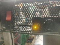
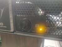
And I have a stupid question about the pics with the 0 to -80dB pot, and the yellow DDT LED glowing. Isn't that pot setting a Limiter Threshold? (I don't know these amps, so just call me stupid and I'll drop the topic! 😉 )
If the Limiter is shunting signal to Ground for any signal that exceeds -80dB, no wonder the DDT light is on!
Cheers
If the Limiter is shunting signal to Ground for any signal that exceeds -80dB, no wonder the DDT light is on!
Cheers
Nope, it is a simple volume control. Instead of 0-10 it is marked in attenuation with zero at the top. Same difference.
DDT is pretty cool and works well enough. It is a clipping prevention system, it does nothing 8until you run the amp past clipping. At that point it just turns you back down unti lyou are no longer clipping. Very much like a regulator on a rental truck, once you get to 55 mph or whatever the governor limits to, you ca keep pressing on the gas pedal but it goes no faster. When you hit the DDT limit, you can turn it up further but it gets no louder. This is preferable to clipping.
DDT compares input to output.
The DDT light simply indicates a loss of feedback (which normally means you’re clipping). This activates the input attenuator. if it’s staying on all the time I would suspect a loss of DC feedback - which usually means the speaker is stuck to the rail. Check the actual output of the amplifier circuit - there may be a protection relay that’s open preventing a reading at the binding posts. Things used to be worse - in the old days they used a crowbar which caused an instant short. And sometimes the transistors would protect the fuses by blowing first.
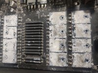
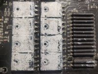
All your pics show the heat sinks pulled. My guess is it’s not safe to run this way, even with light load. You could get bias runaway.
All your pics show the heat sinks pulled. My guess is it’s not safe to run this way, even with light load. You could get bias runaway.
The block of presumably outputs,
Q122-128 66.0 6.6mv 65.5
Q121-127 -65.8 -4.6mv -65.2
Q113-119 -65.5 -9.5mv -64.9
Q114-120 65.7 6.8mv 65.1
looks fairly reasonable, as long as they really are outputs.
Q131 and Q132, on the other hand, do not look quite as healthy . .
But again, hard to say without the schematic.
It would also be really great to see what the output, before the protection relay, is doing. (Someone else already mentioned.) Although, if those really are output-device-Collectors, and they really are all within 10mV of Ground, it may not tell us very much.
Cheers
I suspect that is a floating/swinging rails amplifier, Peavey is known for having used them a lot, even in humble 50W| amps,
In that case collectors ARE grounded.
In that case collectors ARE grounded.
Thanks Enzo.
A BEAST of a amp, 14 power transistor per channel amp, quad rail, switching with industrial strength IGBTs, a monster.
With due respect, way above what can be repaired "just asking at a Forum".
Not many modern Techs (who are used to very different stuff) will be able to handle it either, unless Factory trained by Peavey or veteran >50 year experience old hands such as jonsnell , oldwisetech or of course, Enzo himself who meets all qualifications.
Include wavebourn in that small list, maybe a couple more, not much.
No, I am not including myself there, I work in smaller stuff, say 500W per amp tops.
If available, I suggest sending it to a Peavey AWSC, a factory trained and approved Tech, or somebody who routinely works with such stuff.
Today 3-4kW amps are simply not made that way anymore, which were a tour de force back in the day (10-20 years ago) , but MUCH simpler, lighter, cheaper, efficient Class D amps, period.
That one is a white elephant by today´s standards.
Sorry for the cold shower.
Plus, access to:
But it's been a more fun ride than most cold showers! 😉
- factory jigs like a known-acceptable-at-low-powers substitute heat sink that permits access to the rest of the board, and
- proper subs for odd parts like those 'foot-long' ballast resistors
But it's been a more fun ride than most cold showers! 😉
But it shares a lot in common with the flying rail amps. Output stage is common emitter and the collectors are all tied together. Heat sink is probably not isolated (And runs at speaker out potential).Turns out I had it. No flying rails on this one. It is a commutating amp though.
These amps are actually rather simple. The power amplifier circuitry is NOT very complex. Just a lot of parallel transistors. The only hard part is working on them with that impossible to service “uni-board” construction and all those surface mount parts. But it’s the only way to cram it into 2U.
Give it its due, it does have the rail commutation circuits and unlike some stereo at home, there are a lot of auxiliary circuits for protection and housekeeping.
As with all modern PA amps, the housekeeping circuitry is about half of it. That stuff is easy and it doesn’t fry (but the caps often go bad causing it to get temperamental - replace all the little electrolytics and 99% of the time the gremlins disappear). The rail commutator is very simple sub circuit that can be independently tested - or run without it on low rail until the amp works satisfactorily. And there is only one per side here - there can be as many as three per side on the biggest ones out there.
The actual amplifier circuit is very very simple - complementary cascodes driving big-*** common emitter power darlingtons. All in the feedback loop of an op amp. If it wasn’t for the fact that you can’t get TO half of the circuit while it’s up and running it would be simple to work on. These are pretty much copies of the Crest Pro200 series (about the time PV acquired them, too) with a regular transformer instead of an SMPS.
The actual amplifier circuit is very very simple - complementary cascodes driving big-*** common emitter power darlingtons. All in the feedback loop of an op amp. If it wasn’t for the fact that you can’t get TO half of the circuit while it’s up and running it would be simple to work on. These are pretty much copies of the Crest Pro200 series (about the time PV acquired them, too) with a regular transformer instead of an SMPS.
- Home
- Live Sound
- Instruments and Amps
- Peavey CS4000 DDT light on