First channel of the pearl soldered today. I have a nice short somewhere, would be great if somebody could shortly take the time and help me a bit!
Being a genius, I left out R8 connecting the regulator with the actual amplifying stage to test first the regulator.
Surpassing myself I also forgot to solder Q2 and Q12.
The result was that R2 and R3 start to get cookingly hot (the 3 Watters of the regulator).
After disconnection and soldering in Q2 and Q12: no change (now circuit fully populated).
I don't even get proper voltage of the toroid, seems the voltage completely breaks down because of a short.
Measuring the resistance between PAD1 and PAD2 (where the psu-board leads connect to the pearl) I get a resistance of 9.5 Ohms indicating that the short is after the 2 power resistors (being 4.7Ohms each).
So what's wrong?
First I thought that I soldered the snapin elcos with far too much solder so that it made a short with the above lying ground plane (btw I failed desoldering them ARRGG), however this shouldn't be possible due to the laquer on the pcb.
Shorted diode also nay, since there would be still the 3k32 resistor R5 giving a higher resistance than I measured.
Any tips greatly appreciated! Thanks a lot guys!
Cheers, Hannes
PS: btw the rail (coming from psu-board) is unloaded 39.9V DC.
Probably shot the IRF9610? Maybe exceed the 20V gate source voltage? But how should this be possible with the 10k R6 in front...
Hannes
Hannes
Nobody keen and clever seing my obvious mistake instantly?
Naaah, I think you guys want me to learn? Ok so there will be a analyze/desolder session in the evening...
However if somebody wants to give me a hint...😀 then give it!
Thanks! Cheers, Hannes
Naaah, I think you guys want me to learn? Ok so there will be a analyze/desolder session in the evening...
However if somebody wants to give me a hint...😀 then give it!
Thanks! Cheers, Hannes
Polarity is ok.
Well, what I know now is that the short is after the 2nd 4.7Ohm resistor (R3). After this R3 I measure zero resistance between signal and ground. Resistors R5, R6, R7 measure ok. The IRF has no short (and does not have a connection to ground anyway).
I think one of the big 10mF caps is shorted. I don't know wether this happens now and then, but I see at the moment no other possibility.
I desoldered the R3 and the voltage after the 1st 10mF cap is fine (40V DC).
At least I learned now to measure also the big caps before soldering them in.
Desoldering snap-ins is really a pain.
Cheers, Hannes
Feed the scientists! My pearl does not obey Kirchhoff!
The remaining 2x 10mF elcos are now desoldered. Both are perfectly ok!
Short still there! All resistors connecting in some way to ground are also ok! Fet is ok!
Everything is ok! Though it is shorted!
Cool 😎
Hannes
The remaining 2x 10mF elcos are now desoldered. Both are perfectly ok!
Short still there! All resistors connecting in some way to ground are also ok! Fet is ok!
Everything is ok! Though it is shorted!
Cool 😎
Hannes
Post pictures and schematics with measured voltages, then I or someone else might be able to help.
Oh it's really easy! After R3 I get zero resistance between signal and ground. Both elcos after R3 are now desoldered, R5, R6, R7, R8 measure ok! Fet measures no short.
I can post a pic a bit later! Thanks a lot, Hannes
I can post a pic a bit later! Thanks a lot, Hannes
Zero resistance is not much - if C2 and C3 are out of th e picture, then only C4 has direct contact to gnd and I doubt it is shorted. Sounds like you have a "mechanical" (not component) short somewhere...
C4 is also desoldered (sorry forgot to mention that!).
Heatsink is isolated with a Silpad and a nylon screw...and all pins of the fet (one of them is connected to the case) show resistance of at least 10k to ground.
Thanks a lot! Cheers, Hannes
Heatsink is isolated with a Silpad and a nylon screw...and all pins of the fet (one of them is connected to the case) show resistance of at least 10k to ground.
Thanks a lot! Cheers, Hannes
How about pulling out the most expensive components (transistors) and apply a low voltage with high current. Then the short might suddenly show it ugly face... 😉
EDIT: If you supply something like 2V you can trace your way to the short by measuring different points in reference to supply +. When the voltage diff gets higher, you are closer to the short with your probe.
EDIT: If you supply something like 2V you can trace your way to the short by measuring different points in reference to supply +. When the voltage diff gets higher, you are closer to the short with your probe.
Yeah, a high current psu would be nice! Heat the beast so much it starts glowing.
It's easy to find the short then 😀
Just that I don't have such a psu.
Thanks! Cheers, Hannes
It's easy to find the short then 😀
Just that I don't have such a psu.
Thanks! Cheers, Hannes
Check your standoffs, if they are metal. The mounting holes in the pcb are very close to the groundplane. Mine are isolated with plastic-washers from TO220 mounting hardware.
Did you jumper the two GND points on the board with a piece of wire as you should?
Steen🙂
Did you jumper the two GND points on the board with a piece of wire as you should?
Steen🙂
Thanks for your help!
I don't have any standoffs at the moment - the board is resting on newsprints at the moment.
If you mean the heatsink...that guy is isolated from the fet using a silpad and a nylon screw.
No, grounds are not connected at the moment. But I thought the grounds meet at the output rca-connectors as stated in the pdf?
Cheers, Hannes
Further news: I also desoldered the heatsink and the fet Q1 (the regulator fet).
Further R5 is now also desoldered.
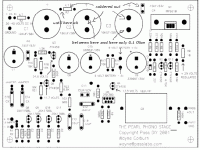
I also attached a new pic with the changes made.
Still shorted
Cheers, Hannes
PS: can I make money with this? Selling it to scientists? Proofing Kirchhoff wrong?
Further R5 is now also desoldered.
I also attached a new pic with the changes made.
Still shorted
Cheers, Hannes
PS: can I make money with this? Selling it to scientists? Proofing Kirchhoff wrong?
Attachments
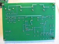
Is is possible for you to take some detailed photos of both sides of your board?
Have you tried making the other channel?
Have you tried making the other channel?
You have to connect the NEG supply from one of the caps to the GND plane (NEG leg on C15, I think, to a solderpad). I will dig out a picture, when I get home. Photos would help, allright.No, grounds are not connected at the moment. But I thought the grounds meet at the output rca-connectors as stated in the pdf?
Steen🙂
- Status
- Not open for further replies.
- Home
- Amplifiers
- Pass Labs
- Pearl shorted...please help me out of this!