Hi,
I am interested to hear from all who have built and/or listened to the Pearl phono preamp before I start gathering parts. Thoughts on parts selection? Construction experience, advice, or cautions? How does it sound in your system? Did you use the suggested ps design or something else?
Thanks!
I am interested to hear from all who have built and/or listened to the Pearl phono preamp before I start gathering parts. Thoughts on parts selection? Construction experience, advice, or cautions? How does it sound in your system? Did you use the suggested ps design or something else?
Thanks!
Pearl grounding questions...
I've ordered all the parts (I think) to build the Pearl phono preamp, and I have a question about grounding for those more knowledgable about electronics than I am.
I plan to put an IEC AC connector on the power supply module that Wayne suggested and connect that ps chassis to "earth" ground (3rd wire). Then, I am planning to put a copper mesh shield over the DC umbilical cord and connecting that mesh shield to the "earth" ground at the ps chassis. Wayne recommended bringing the two DC grounds together at the signal output, and connecting them to chassis ground at that point.
My question is: do I attach the umbilical shield to the phono pre chassis as well?
a) If not (to my understanding) that would leave the phono pre chassis floating with respect to earth ground.
b) If so, wouldn't noise on the "earth" ground find its way into the signal output from the Pearl?
I am concerned with safety first and then sound; I welcome any thoughts / advice on the subject.
Grounding
We connect the earth ground to the circuit through a power thermistor, this gives several ohms resistance; effectively breaking ground loops while still protecting against electrical faults.
SAFETY FIRST! It matters little how good your system sounds if its lethal.
Cyclotronguy
We connect the earth ground to the circuit through a power thermistor, this gives several ohms resistance; effectively breaking ground loops while still protecting against electrical faults.
SAFETY FIRST! It matters little how good your system sounds if its lethal.
Cyclotronguy
Thermistor value?
Thanks.
I searched this forum and found some references that talk about using inrush limiters as safety devices as you mentioned. Generally everything is a trade-off, but what is a reasonable value thermistor to use for this purpose? I assume I want one that will go to ~ zero ohms fairly quickly in a failure situation, so maybe a 5 or 10 ohm thermistor?
Regarding shielding the phono leads, I am not planning anything other than keeping the leads short... maybe 1 inch. Since there isn't any AC in the phono preamp chassis I am not expecting problems. But that's the advantage of ignorance... I won't ever expect problems.
Ren
please explain
How does a thermistor protect you from an electrical fault? If such a fault existst, you want want to shunt it to ground through the thermistor. But then the thermistor gets hot and the resistance quickly increases until the time when you touch the metal case and get a nice shock because there's no longer a good ground shunt, and the thermistor didn't let enough current through to blow the fuse. What am I missing?
Evan
Two types of thermistor - you're thinking of the wrong one. Resistance goes down with increase in temp for the right one.
Jake
Jake
Thermistor
"Thermistors:
The term "Thermistor" is used to describe a range of electronic components whose principle characteristic is that their electrical resistance changes in response to changes in their temperature.
The word "Thermistor" derives from the description "thermally sensitive resistor".
Thermistors are further classified as "Positive Temperature Coefficient" devices (PTC devices) or "Negative Temperature Coefficient" devices (NTC devices).
PTC devices are devices whose resistance increases as their temperature increases.
NTC devices are devices whose resistance decreases as their temperature increases.
NTC thermistors are manufactured from proprietary formulations of ceramic materials based on transition metal oxides."
The idea is to use a NTC type to have a low resistance during a fault condition and a higher resistance during normal operation when you don't want your signal ground closely coupled to earth ground.
H.H.
My recommendation is to keep the audio signal disconnected completely from the chassis. I did this and have not bee shocked yet.
So in effect, the RIAA floats and is effectively set by the next stage. As such, it is important to have separate power windings for each channel.
Petter
So in effect, the RIAA floats and is effectively set by the next stage. As such, it is important to have separate power windings for each channel.
Petter
separate secondary windings...
I am using a toroidal transformer with separate secondary windings for each channel.
Regarding the shock hazard, I think you're right and maybe I'm making too much of this. But my concern is not the 99.999% of the time when every component is functioning as designed. I'm concerned that the thing doesn't become a fire hazard or shock hazard if a component fails. Call it insurance.
Ren
You could use 1-10K for ground, or any combination of diodes in antiparallell (high resistance to low current), just make sure you put them to the chassis at the exact same point so no current can flow in chassis!
A floating chassis is not a fire hazard per se. You could ground the chassis to electrical ground if you prefer, and in this case I would strongly suggest that you don't ground the signal at any point.
Since output is capacitive coupled there should be very little risk if any to this approach. The real risk with the Pearl is breakdown of input transistors which will likely fry the cartridge.
Petter
The original question was: What do you think?
Well, the Pearl seems like a good unit. It surely does not have enough gain for MC pickups, but I remedied that by using more transistors -- and through tight matching of devices reduced source resistors from 22 to 18 Ohms. I guess I could have gone even lower.
If you need to drive MC pickups, you need more gain -- much more, at least 5 times as much if not more still.
I build a variation of the power supply -- several stages of passive filtering + cap multiplier on both input and output (original only had this in input).
Sound was good.
Petter
Petter,
I am inthe process of building the Pearl could you share your design changes with us. I would like to compare your changes with some I am planning.
We all have to thank Wayne for doing an excellent job in the original design.
Jam
I am inthe process of building the Pearl could you share your design changes with us. I would like to compare your changes with some I am planning.
We all have to thank Wayne for doing an excellent job in the original design.
Jam
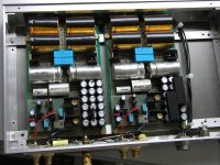
I did not built Pearl but did the Ono (just the output stage without MC part). For anybody wanting more gain from Pearl the Ono output stage might be of interest. It's easy to built and doesn't require coupling cap. The small board in left corner of mother board is my implementation of this circuit. You don't see resistors because they are on the other side. The PS transformers are separate.
Attachments
Where does he get all those wonderful chassis?
Peter,
For once I would like to see you build something in a coffee can or cigar box so as the rest of don't feel so bad. 😀 😀 😀
Keep up the good work.
Jam
Peter,
For once I would like to see you build something in a coffee can or cigar box so as the rest of don't feel so bad. 😀 😀 😀
Keep up the good work.
Jam
HPotter's Ono
Even more than the chassis, I like the caps that say "free sample" on them. I think we all want them!😀
Even more than the chassis, I like the caps that say "free sample" on them. I think we all want them!😀
- Status
- Not open for further replies.
- Home
- Amplifiers
- Pass Labs
- Pearl phono preamp questions