+/-25.1 VDC unloaded. that is very reassuring. thanks.
4R7 filter resistors in mine. I shipped 10R in the kits. I Obey to the BOM
... sorry is it for R5-8 ? if yes, i have put 4R7
Loaded I get + 21.7 / - 22.1
24-25V unloaded (without the pearl 3 RIAA box attached) is perfectly normal.
20-22V loaded is also normal. The P3 boards will use the onboard regulators to get the voltage to +/-15V. i got that now... awating two cables to plug the phono boards...normally i should have them today.
LED resistor Values
The values don't need to be too exact. You can go "rule of thumb" 1k Ohm per volt on the PSU. So 20-25k is fine. I shipped 10k with the group buy parts kits because that's the LED value in the P3 kit. This will result in the same LED configuration in both boxes assuming the same LEDs are used. I paced the 24K9 and as mentionned D4 was weak... i have unsoldered all leds and awaits new ones today aswell... I replaced the R9 to 11 by 4K75
Snubber resistors
I see you have snubber caps installed, but not snubber resistors. You can install 68R resistors for R1 & R2. I have no idea how the circuit reacts with only partial implementation of snubbers. Well I made the quasimodo but have no oscillo accessible to me right now... A friend advised between 50 and 100 R... only 82.5R (?!) were awailable in this range on the site i ordered them from so i went for that...
Can you measure again: I will as soon as i soldered the new leds...
Output GND to output +
Output GND to output -
Output + to Output -
Output GND and both sides of R9 - 11
Please confirm the resistor values you used: as the BOM says
R3-4 3K 1W
R5-8 4R7 1W
R9-11: first 24K9 now 4K75
R3-4 3K 1W
R5-8 4R7 1W
R9-11: first 24K9 now 4K75
These are all good.
82R5 for R1&2 - also good. Anything 50-100R is good.
I hope the new LED's will light up for you, too!
Some reassurance for you... The external power supply board is CRCRC with a snubber circuit. The snubber knocks down any transformer / rectifier ringing interaction. The CRCRC will result in very low ripple voltage to the main phono box. Then the phono box has regulators which set the voltage and further reduce noise. And then Wayne designed in a cap multiplier, which further reduces noise. Starting with the default design will deliver great results.
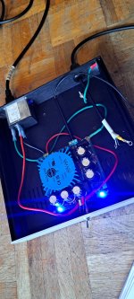
Thank you so much for taking the time... Yes it did light up ! R1 and R2 soldered and contuinity across all sides of the chassis checked ! here are the measurements
Can you measure again:
Output GND to output + +24.22V
Output GND to output - -24.38V
Output + to Output - +48.5V
Output GND and both sides of R9 One side : 2.73V the othe side: 24.26V
- 11 One side 24.26V the other side 2.86V
Attachments
Not quite !
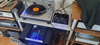
I just plugged the phono boards.
i have +/- 21.32 V at the psu now so that s good. all leds lights up that s also fine.
BUT I originally had 2.3 V on R27... The only resistor that would just do about I had at hand was a 400R... so i unsoldered the 220R, and remeasured and i find 2.6 V !!! so no quite ! ... so close i can t beleive I'm gonna have to wait delevery of two minuscule Rs....
Last edited:

- Home
- Amplifiers
- Power Supplies
- Pearl 3 power supply