Re: Go, Bernhard, go
Just the thing to go with KBK's revolutionary clock, I suppose.carlosfm said:
Let the guy play, it's fun.😀
He will eventually make a revolutionaty design with a pre-historic chip...
rudi
Do you think this stacking would work as well with a more modern DAC with voltage out?
See:
http://www.diyaudio.com/forums/showthread.php?s=&threadid=52449&perpage=10&pagenumber=2
I am so pleased with the sound now.
Its an akm4383 DAC.
I would try a 2-4k matched resis. on each v output?
Then connect all the other pins together?
What do you think?
Lewis
rudi
What type of I/V does you DAC use? Presumably if it was passive, you'd have to change the resistor value?
Regards,
Jonathan
What type of I/V does you DAC use? Presumably if it was passive, you'd have to change the resistor value?
Regards,
Jonathan
jdunham said:rudi
What type of I/V does you DAC use? Presumably if it was passive, you'd have to change the resistor value?
Regards,
Jonathan
Hi Jonathan.
I am still using the standard passive onboard I/V and i haven't changed anything else, just added the chips
Anyone there??
fumihiko:
What do you think about stacking a DAC like akm with diff. voltage out?
Lewis
fumihiko:
What do you think about stacking a DAC like akm with diff. voltage out?
Lewis
What do you think about stacking a DAC like akm with diff. voltage out?
There is an effect in making DELTA SIGMA DAC parallel.
The voltage output can be easily summing up by the resistance.
if 4 paralling up voltage output DA chips
load-resistance in 1/4 of the specified value
To protect, it makes a low-resistance (47ohms to 100ohms)series in each DAC chips.
summing point is a load-resistance
a loss by the resistance but the effect which depends in parallel exceeds.
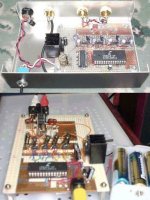
it's my latest project, 4paralled CS4340 with resistance summing up
and 4paralled CS4331 test head
Attachments
Re: Anyone there??
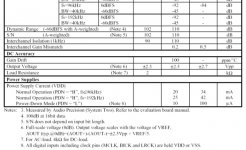
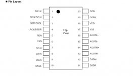
See the AD1852 datasheet. Fig.28 shows how to sum parallel voltage outputs.
ljordan said:fumihiko:
What do you think about stacking a DAC like akm with diff. voltage out?
Lewis
See the AD1852 datasheet. Fig.28 shows how to sum parallel voltage outputs.
See the AD1852 datasheet. Fig.28 shows how to sum parallel voltage outputs.
inverted summing application,it's best solution.
but need dual power supply😉
My experiences
OK, tried the mod (using Rudi's method of using an adaptor)and have had it running for a couple of days now.
Initial impressions are of:
More detail, especially very low level stuff like the sound of a singer's dry lips parting at the start of her singing or the sound of other band members preparing to play (the double bass being moved etc) or a myriad other little details. Basically, this info was below the systems noise floor before. So maybe there is some truth in the square-root of 2 enhancement...
More layering-It has become easier to follow different layers-seperated yet integrated with the whole.
More depth and staging.
The big issue here is that the volume virtually doubles and one has to try to adjust for that in order to perofrm meaningful A-B comparisons.
Not sure about using 3-maybe someone else can post their experiences with more DAC's?
FWIW,
Ryan
Jusy had a look at data sheets. PCM56 is 16 pin for a start. Ryan is kindly having a look at it with a view to providing some suggestions. I would welcome input from anyone else who would care to have a look. Strangely enough, PCM56 does not seem at all difficult to find. Does anyone think it will make much difference if the standard grade part is used? (PCM56P)
Pcm 63 piggyback mod problem
Hi
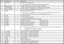
I`ve modded a pcm63k by disabling pins 1,3,4,9,10,23,24,25 and adding oscon 10V 4.7uf caps betweeen pins 1>28, 3>7, 4>7, 23>7 and 24>7 (7 is ground). w/ the modded chips installed, my dac frequency lock light glows, but there is no click from the Siemens relay and the mute fails to disengage.
also...
w/o the oscon caps installed, the chip piggybacked straight onto my existing pcm63 produced sound, but there was considerable dc offset, the woofers moved in and out w/the volume control (muusic not playing) and produced a muffled sound
Any suggestions much appreciated.
Bill
Hi
I`ve modded a pcm63k by disabling pins 1,3,4,9,10,23,24,25 and adding oscon 10V 4.7uf caps betweeen pins 1>28, 3>7, 4>7, 23>7 and 24>7 (7 is ground). w/ the modded chips installed, my dac frequency lock light glows, but there is no click from the Siemens relay and the mute fails to disengage.
also...
w/o the oscon caps installed, the chip piggybacked straight onto my existing pcm63 produced sound, but there was considerable dc offset, the woofers moved in and out w/the volume control (muusic not playing) and produced a muffled sound
Any suggestions much appreciated.
Bill
What make is the unit? If you have an opamp based i/v stage disabling pins 9 and 10 isn't a good idea, if you are not certain the internal feedback resistor is not in use. Also check pin5. If it is not connected or grounded it changes the idle point of the dac and that may cause a DC offset further down the line.
Thanks for the quick response - the dac is a Polyfusion 800. I`ll check pins 5,9 & 10 - i suspected it might be the latter 2 as the schematic for the chip shows them directly leading to the output stage (BB2604`s, in my case). Will post back w/results.
Bill
Bill
pins 9 and 10 it was - data locks, muute disengages, and music plays w/ these pins in use, but dc offset persists - any suggesed remedies?
Bill
Bill
billinjapan said:pins 9 and 10 it was - data locks, muute disengages, and music plays w/ these pins in use, but dc offset persists - any suggesed remedies?
Bill
How many volts is the offset? Connecting pin 5 to the output should make the dac idle at 0v.
- Status
- Not open for further replies.
- Home
- Source & Line
- Digital Source
- pcm63pk in piggy back mode.