Hi, I did my first passive conversion with pcm56k and there is very much audible distortion. It increases with the music volume and decreases when the music is quiet.
I used this setting: I output: 750R i/v
The filter is 18 R in series and 0.1uf in //
There is also a 22uf output cap in case of DC current.
I saw schematics with 1k resistors so I choose 750R , lampizator uses 500R, and some other people use only 50R - 100 R. I might try 375 now.
Peace. Please answer only if you have a pcm56 I output resistor and knows what value is best for output level vs distortion.
For the others I noticed a funny fact: distortion sounds like 5 % - 10 % depending on output level, well with classical its very apparent, piano, midrange etc. BUT when I listen rock or electric guitar or Michel Jackson it's sounding ok – disco too.
18 ohm + 100 nF ? where did you see that ?
That is more or less the same as if you shunt the Iout directly with 100nF to ground
Can not work.
Analog filter for a single PCM56 per channel, 200 ohm I/V:
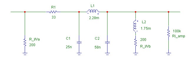
Or for a 750 ohm I/V:
put 10nF ll to R_I/V.
No series resistor.
That is more or less the same as if you shunt the Iout directly with 100nF to ground
Can not work.
Analog filter for a single PCM56 per channel, 200 ohm I/V:
Or for a 750 ohm I/V:
put 10nF ll to R_I/V.
No series resistor.
Hi Bernhard ! Thanks for helping. I have 3 questions concerning your post.Bernhard said:18 ohm + 100 nF ? where did you see that ?
That is more or less the same as if you shunt the Iout directly with 100nF to ground
Can not work.
1.
The 18 R + 100nf are to do a first order LP filter... Why it cannot work ???????
This afternoon before I saw your answer I used 375 R for I/v and the distortion was mostly gone.
2.
Do you use the schematic in the picture ?
3. Now my problem is with the BASS, it is cut, what is the possible explanation ??? Is it because the 375 R is too low and cut bass ? I heard that some people say it’s more bass when the resistor value is higher...
Gabdx1 said:
Hi Bernhard ! Thanks for helping. I have 3 questions concerning your post.
1.
The 18 R + 100nf are to do a first order LP filter... Why it cannot work ???????
This afternoon before I saw your answer I used 375 R for I/v and the distortion was mostly gone.
2.
Do you use the schematic in the picture ?
3. Now my problem is with the BASS, it is cut, what is the possible explanation ??? Is it because the 375 R is too low and cut bass ? I heard that some people say it�s more bass when the resistor value is higher...
1. 750 ohm ll Z of PCM56 give 455 ohm.
With 18 ohm and 100n you have -15dB @ 20 kHz.
Those values are totally wrong.
2. No, I made that schematic for a forum member, but I use a similar higher order filter.
3. I use 250 ohm per chip and bass is very good.
Are you sure that everything else is ok ?
Did you build a DAC or mod a player ?
Internal opamp disconnected correctly ?
Yes, I don't know how to calculate a filter and don't know how to calculate the Z at the output...
I modified a player, I already broke my old Sony by modifying it, and I posted that in another part of forum. This is the dbx5.
Everything is fine, no opamps, no pop or noise.
I try to build a first order LP and set the i/v resistor to good value and I aim for around 1/4 of power of the normal cd player, more is ok.
I think ill try it with 100 R for i/v, but what is the value I should use for the cap and resistor of the filter???
Right now I can't build that complicated filter in picture because I don't have a PCB right now.
Regards
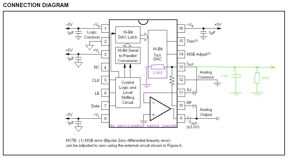
You could try 500 ohm for I/V + 13nF parallel.
That should be a good compromise.
Did the player use the internal opamp of the PCM56 ?
All connections removed ?
Pins 9, 10, 10 open / not connected.
That should be a good compromise.
Did the player use the internal opamp of the PCM56 ?
All connections removed ?
Pins 9, 10, 10 open / not connected.
Yes the player used the internal opamp, I didn't disconnected 9 - 10.
I have a problem :::::::::::::::::::
I tried it on my more sensitive system just with woofer speaker connected: unfortunately there is 3 mV 60Hertz pollution signal at the output of the dac , it is continuous even when the power is off !!!!, I need to disconnect the cd power cord to stop that 60 hertz pollution ...
That’s a huge problem ... Ill try to disconnect pin 9 and 10
I have a problem :::::::::::::::::::
I tried it on my more sensitive system just with woofer speaker connected: unfortunately there is 3 mV 60Hertz pollution signal at the output of the dac , it is continuous even when the power is off !!!!, I need to disconnect the cd power cord to stop that 60 hertz pollution ...
That’s a huge problem ...
Ill try to disconnect pin 9 and 10Bernhard said:
Pins 9, 10, 10 open / not connected.
Sorry, I made a typo:
9, 10, 11 all must be disconnected.
Most important: 9 must be disconnected from 10

Ok, I had disconnected pin 11- 13 already
I didn't thought that disconnecting pin 9 - 10 was necessary but I will do it.
I didn't thought that disconnecting pin 9 - 10 was necessary but I will do it.
I did not disconnect pin 12 of the circuit, I just added a wire on the pin. The only trace I cut is pin 13.
Should I disconnect pin 12 of the original circuit????
Should I disconnect pin 12 of the original circuit????
In the datas BB stated 200ohm IV resistor...
But, I useed 100 ohm resistor Riv to gnd.
with loaded OP (which is inside...) out of 2-3K
and without overheating dac chip...
*
addopted hafler based transistor OP as voltage amplifier
after to output...
PMD100 before dac...
*
I found 56' excellent really
But, I useed 100 ohm resistor Riv to gnd.
with loaded OP (which is inside...) out of 2-3K
and without overheating dac chip...
*
addopted hafler based transistor OP as voltage amplifier
after to output...
PMD100 before dac...
*
I found 56' excellent really
Zoran said:In the datas BB stated 200ohm IV
200 ohm, where ?
In the datasheet, settling time is specified for virtual ground and for 1k passive I/V.
in original datas, not directly,
but like test conditions in the parhensis?
I am 98% positive, burt I will try to find more specific...
but like test conditions in the parhensis?
I am 98% positive, burt I will try to find more specific...
Anyway, everything below 1k is good, less is better, also because it gives a lower output impedance without need for a buffer.
--> parallel chips
--> parallel chips
Bernhard said:No. Red is cut, green is add.
Bernard
Thanks for the schematic. You made it very simple to understand.
I'm curious. Given the 1160 ohm internal resistor you show ; how would it work with only a small ll cap ,then directly out?
- Status
- Not open for further replies.
- Home
- Source & Line
- Digital Line Level
- PCM56K iv resistor value?