Hi guys,
Yet another PC2707 USB module and I can't seem to get Windows to Detect it 🙁
I gives me error where It says that there is a problem with my USB device.
I checked all the connections from the chip to the components and the PSU.
What I did:
1. Checked if my and gate works to pull up D+. It does pull it up when it detects Vusb and 3.3V for the DAC. D+ stays Hi once on.
2. Swapped 3.3v sourses. Used a PC PSU for the 1st and went to a 3.3V LDO for the second.
3. Checked the clock.... I can seem to get a readout from the clock on my Oscilloscope :/. I have a 20Mhz Hitachi Tracer Beam Oscilloscope measuring this 12Mhz clock. I can't get a sine wave to show when using the 10x probe. I only see a DC voltage when the scope is DC coupled :/.
I opened up a small USB DAC based on TAS2012 or something that uses the same type of clock but it is 6Mhz and my scope was able to see a nice clean Since Waveform. the 12Mhz on my board I cant see with the scope :/
I swapped the clock with another and the same thing!!!
Wrong capacitors on the clock? Mine is 33pf.
4. Swapped the PCM2707! it was a pain but i cut all the pins and took the thing out. Lifted some pads, but luckily the ones that lifted were the Non Connected ones, except for the D+. I had to bridge D+ to the resistor with a wire.
5. Checked the Host pin and it looks like it's pulled correctly via Vbus. That is straight out of the datasheet.
After swapping the CLOCK and the CHIP out nothing changed. I get the same windows message of malfunctioning USB device.
Any ideas guys?
Anything wrong with the schematic?
Attachments
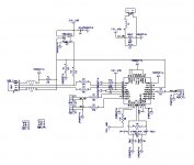
Corection, I am using 30pf Ceramic NP0 Caps for the clock.
The datasheet states a 20pf capacitor for this clock.
However, I did a ton of research way back when on selecting those caps and picked 30pf. Also the AMB Gamma 1 DAC also uses the same crystal with 33pf caps?!?!
The γ1 Modular Miniature DAC
hmmm.... idk, I am going over my schematic and I can't find anything this far 🙁
HOST is good
FSEL is good
PSEL is good
or are they?
Update:
Found one mistake.... my TEST pin was unwired because my schematic had 3.3V_USB and VDD. This fixed the oscillator and I can see a sine wave now!!!
But it still can't recognize the the Device. It selects it as an Unknown device.
Found one mistake.... my TEST pin was unwired because my schematic had 3.3V_USB and VDD. This fixed the oscillator and I can see a sine wave now!!!
But it still can't recognize the the Device. It selects it as an Unknown device.

I am back from vacation and was able to take a look at the USB module
... guess what guys (if anyone is reading)... I flipped the D+ and D- wires on the USB cable..... great!!!
From what I've read that mean that the chip is fried... good thing I had samples. Need to order the supplemental parts, repopulate the 2nd PCB and will try this again :/ lol
So 1 mistake on the schematic and 1 brain fart.
Finally got around to it again last night and...... detected by Windows 7!!!! 🙂
It took about 5 min to go trough the schematic and to discover that I have also left off the Vccp floating. I believe I got confused that Vccp was only powering the analogue part of the PCM2707 which I didn't need and I left it open. Of course Vccp powers the oscillator and one more periferal.
So there you go... now to my ASRC dac part... checking my pins there as well... for stupid mistakes.
- Status
- Not open for further replies.