Im trying to design my first DAC and I decided to use a PCM2702. I have some questions about some of the specs though. I see in the spec sheet that it's analog output is 62% VCC and it's Center Voltage = 50% VCC. Am I correct in understanding that the outputs are ~=3VAC and DC biased at ~= 2.5VDC? If so, what is the proper method of implementing an active filter. Leave the DC bias and use a single supply op amp configuration? Or, drop the DC using a coupling cap and use either a dual supply or VGND configuration?
Thanks,
Daniel
Thanks,
Daniel
I was looking at the documentation for the TI evaluation board. It appears that they use a single supply setup and remove the DC after the filter... I have another question however. It appears to me that they use the SSPND ouput to light an LED. It looks like the LED is on when SSPND is low, indicating a fault. How can I use it for a power LED? Use an NPN?
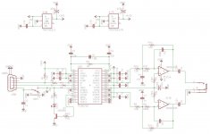
Can someone look over this design and let me know if it looks ok. I'm using an OPA2132PA op-amp to match the one in the amp I'm using. I added an equivalent resistor to the NI input of the filter. I'm using an NPN transistor to drive a power LED. I also wanted to use a PP 1u cap on the output instead of a 10u electrolytic. The volume pot on my amp is 10k, which makes a high pass corner freq. of ~=16Hz I think...
Attachments
Well here's the final product...
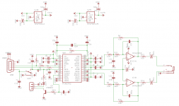
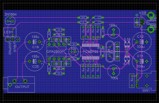
I've included the final Schematic and Board layout also. If anyone is interested.
I had a lot of fun with this project, first time with SMD and also first time doing re-flow.
This thing sounds fantastic! The only thing that I can complain about is the turn-on/off pop. Not sure about the cause yet.
Matches my amp nicely as well...
An externally hosted image should be here but it was not working when we last tested it.
I've included the final Schematic and Board layout also. If anyone is interested.
I had a lot of fun with this project, first time with SMD and also first time doing re-flow.
This thing sounds fantastic! The only thing that I can complain about is the turn-on/off pop. Not sure about the cause yet.
An externally hosted image should be here but it was not working when we last tested it.
Matches my amp nicely as well...
Attachments
The pop is caused by the output capacitors charging (which causes current to flow at the amp input, creating a temporary voltage).
Larger caps have worse pop because of the increased current to charge them (I think), but smaller caps have the low end roll-off, so it's a trade-off. You could add a buffer between the output caps and the input of the amp. That would allow really small output capacitors and would remove the volume pot from the low end roll-off equation.
Very nice layout!
- Status
- Not open for further replies.