This issue specifically appears when the filtering stage is handling a higher signal level. Is this reflective of reality though? I can't really see a reason why this should be, the loading on the op-amp is more variant but won't drop too low because of the R component in the filters.
I followed the advice given by keantoken in this thread about how to produce meaningful FFTs for audio in LTspice and have achieved a more believable result:

Well, in fact the THD+N is too low for this Op-amp but at least the two arrangements now produce matching results and so I have pursued the single stage arrangement, set to produce 4.2V RMS output at 0dBfs. This is approximately the level used in testing the CS3318 for its THD+N figure and so should produce optimal results. For now I will assume sending the output at this level (and balanced) with 4:1 turns ratio transformer at the receiver (Sowter 4383 looks ideal, cost is still ouch!), then a power amp with typical gain will be driven to clipping at something like -6dBfs with the CS3318 set to 0dB (maximum applied in software).
On the PCB I have updated the resistor footprints to 10mm style which is more comfortable and replaced the 3.9k with 8.2k for the additional output gain.
I have also created the Gerbers according to this guide and taken a look in GC-Prevue, it looks good to me, certainly no mirrored layers or anything silly. I have intentionally added the values to my silkscreen and the outlines for the SMD passives, looks nicer to me, maybe I'm just used to seeing them! If anyone experienced wants to take a glance that would be great confirmation too! The GC-Prevue file is also included.
Thanks 🙂
Attachments

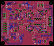
I noticed a couple of things, principally a misplaced via and the silkscreen for some SMT parts being over the solderable area. I have revised these and attached the latest Gerbers in the format required by OSH Park who I think are cheapest for just a few of these.
Just a couple of concerns:
Here's what I'm seeing in the viewer:

Comments appreciated!
Just a couple of concerns:
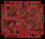
- The GC-Prevue viewer fails to load the Bottom silkscreen (GBO) layer and reports an error. With no parts mounted on this side of the board this file is in fact empty, is this the cause of the error and will OSH Park still want that file?
- The GC-Prevue reports a warning of zero and/or negative tool width for many of the layers, which apparently is caused by the board outline or hole outlines. I adjusted the board outline to have some thickness but still this warning appears. Looks fine however so perhaps it's no real issue?
Here's what I'm seeing in the viewer:
Comments appreciated!
Attachments
Check out some of the videos here.
There is one for getting your gerbers
ready for manufacture.
I use LaenPCBOrder.dru design rules when drawing my board, Silk.ulp for
setting up my silk screen layers and LaenPCBOrder.cam for generating my
gerbers.
There is one for getting your gerbers
ready for manufacture.
I use LaenPCBOrder.dru design rules when drawing my board, Silk.ulp for
setting up my silk screen layers and LaenPCBOrder.cam for generating my
gerbers.
Last edited:
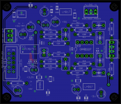
Here is a set of gerbers for something I had made at OSHpark.
They might be useful for seeing how everything was named
and what layers were used.
They might be useful for seeing how everything was named
and what layers were used.
Attachments
Last edited:
Thanks for that, I've made a few small changes and re-processed the CAM with LaenPCBOrder.cam. I don't suppose the solder paste layer is required, did you send it anyway?
I've increased the silkscreen size as I read they are printed at 200DPI, so at the original size this is barely legible.
Perhaps more importantly I've shaved the dimensions down a fraction to bring the total area to slightly under 6 square inches 😉
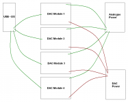
My main concern now is really with running 3 or 4 of these boards together and the potential to spoil the grounding when doing so (crudely shown in MS Paint graphic!). I feel as though integrating 4 onto a single PCB, ideally along with the CS3318 controller, will work better but this will be beyond the extents of the Eagle lite version 🙁
Latest Gerbers are also attached 🙂
I've increased the silkscreen size as I read they are printed at 200DPI, so at the original size this is barely legible.
Perhaps more importantly I've shaved the dimensions down a fraction to bring the total area to slightly under 6 square inches 😉
My main concern now is really with running 3 or 4 of these boards together and the potential to spoil the grounding when doing so (crudely shown in MS Paint graphic!). I feel as though integrating 4 onto a single PCB, ideally along with the CS3318 controller, will work better but this will be beyond the extents of the Eagle lite version 🙁
Latest Gerbers are also attached 🙂
Attachments
I only send layers that are needed.
The solder paste layer is used to manufacture
the metal "silk screen" used to apply the solder
paste.
The solder paste layer is used to manufacture
the metal "silk screen" used to apply the solder
paste.
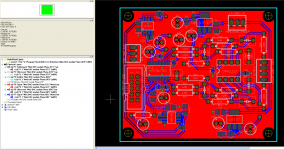
You can get rid of viewer.gwk and tcream.ger from your .zip.
When you upload the file to OSHPark, it will do a quick design
rule check and generate a preview of the top and bottom of
the board as it will look when done. You can do this over and
over to check your files or board.
p.s. I liked your music.
When you upload the file to OSHPark, it will do a quick design
rule check and generate a preview of the top and bottom of
the board as it will look when done. You can do this over and
over to check your files or board.
p.s. I liked your music.
Dr_Em.
Any chance you could post the Eagle-files..?? just to have something to play with
michael
Any chance you could post the Eagle-files..?? just to have something to play with
michael
Thanks, it checked out on that circuitpeople website just fine, quite handy that! I think it is production ready 😀
Hi MiiB, I can send them over but I'll have to go through and find the relevant libraries too, I even modified the standard '.resistor' library with these new tPlace outlines so I'd recommend keeping a backup of your existing one. What were you thinking to modify on the design? As I mentioned earlier, what I'd really like is to get all the DACs onto a single larger board.
p.s. Thanks Avro! I think it has limited appeal but I like making it, it's the sort of
thing I'm into myself at least! Big fan of Prodigy and Massive Attack, among others.
Good luck with the build...I hope it sounds good, you put a lot
of work into it.
You might like some of the artists on the Lagunmuch label
I like Night Tech and OID among others.
Also Divinorum (Bjorn Lynne) and Sphongle.
Sorry for the off topic...
of work into it.
You might like some of the artists on the Lagunmuch label
I like Night Tech and OID among others.
Also Divinorum (Bjorn Lynne) and Sphongle.
Sorry for the off topic...
I was thinking to make a different and discrete analog stage, and maybe also do some changes to the power supply section. would not mind to share back with you, both the Sim files and the eagle files afterwards.
I would really prefer the current output version 1792. I have heard this dac in some wonderful applications. (different project though)
I would really prefer the current output version 1792. I have heard this dac in some wonderful applications. (different project though)
I sent you a PM MiiB, your ideas do sound interesting! I was initially looking at the 1792 (1794) DAC but the extra IV stage meant 2 extra op-amps and all the PCB area that comes with it. In practise, 113dB SNR should yield an inaudible noise floor in any listening scenario, although I'll admit it is nice to have a DAC which can claim 129dB SNR! The THD is about 6dB lower too.
As I say, my main concern is the grounding of multiple units and I would really like 4 of these on one board area along with the CS3318. It may be possible to meet spec with modular units like this but I think it'll be less predictable. Very annoying that even the standard/hobbyist Eagle has a board area limited to 100x160mm, as if it was 'unlimited' I would consider the upgrade.
As I say, my main concern is the grounding of multiple units and I would really like 4 of these on one board area along with the CS3318. It may be possible to meet spec with modular units like this but I think it'll be less predictable. Very annoying that even the standard/hobbyist Eagle has a board area limited to 100x160mm, as if it was 'unlimited' I would consider the upgrade.
Hi all, bit extreme but I've created an 8-channel design within the board area limitations of Eagle, using PCM4104 DACs. I am more confident about performance of a single PCB multi-channel design than multiple stereo ones sharing I2S.
This design has been interesting and I look forward to seeing what you may come up with MiiB! The design should work great for anyone requiring just stereo. I've taken input from this thread forward onto the new design so perhaps it won't need many changes.
It's here if anyone is interested!
http://www.diyaudio.com/forums/digital-source/242668-new-dac-pcb-dual-pcm4104-8-channels.html
p.s. Arvo, can't really call it off-topic since we're on DIY Audio and all of what we do should center around the music! Did enjoy some of the tracks on there, thanks 🙂
p.s. Arvo, can't really call it off-topic since we're on DIY Audio and all of what we do should center around the music! Did enjoy some of the tracks on there, thanks 🙂
Your welcome!
- Status
- Not open for further replies.
- Home
- Source & Line
- Digital Source
- PCM1793 PCB Layout