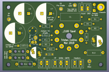
I'm planning on making a simple, compact SE PCL82 amp for the kitchen / office. For ease and speed I'll get some PCBs made up using PCBway (10 for $5).
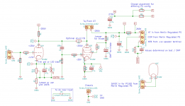
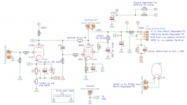
Attached is my attempt at a design featuring:
- pads for GNFB
- pads for shunt (plate to plate / Schade) feedback
- driver stage bias by trim pot or LED
- pads to allow both triode and pentode connected power stage
- alternate B+ chain
- plenty of test points
- should be usable for both ECL82 & PCL82
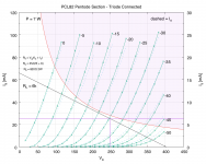
Initial component values are shown on the schematic (based on PCL82 measured curves taken with a uTracer). I'll have plenty of scope to tweak on test.
The HT and heater supply will come from one of Merlin's regulated power supply boards. OT are old, tiny ones from eBay. PS is a custom toroidy.pl left over from another build.
The kitchen amp will use two boards for stereo, the PS board and an additional PS relay board (to be designed) to give a 5V supply and control the overall power state via a Raspberry Pi Zero.
I hope to use one of the extra boards as a test bed to have a go at tuning the GNFB / square wave response / Schade etc etc.
Can anyone see any issues?
Tristan
Attached is my attempt at a design featuring:
- pads for GNFB
- pads for shunt (plate to plate / Schade) feedback
- driver stage bias by trim pot or LED
- pads to allow both triode and pentode connected power stage
- alternate B+ chain
- plenty of test points
- should be usable for both ECL82 & PCL82
Initial component values are shown on the schematic (based on PCL82 measured curves taken with a uTracer). I'll have plenty of scope to tweak on test.
The HT and heater supply will come from one of Merlin's regulated power supply boards. OT are old, tiny ones from eBay. PS is a custom toroidy.pl left over from another build.
The kitchen amp will use two boards for stereo, the PS board and an additional PS relay board (to be designed) to give a 5V supply and control the overall power state via a Raspberry Pi Zero.
I hope to use one of the extra boards as a test bed to have a go at tuning the GNFB / square wave response / Schade etc etc.
Can anyone see any issues?
Tristan
Attachments

You need to ensure that the feedback is referenced to the same point as the input, so some sort of connection between speaker -ve and GND/GNDA is needed. Ideally this connection would follow the same route as the +ve speaker to feedback, so the loop area is small.
so some sort of connection between speaker -ve and GND/GNDA is needed. Ideally this connection would follow the same route as the +ve speaker to feedback, so the loop area is small.
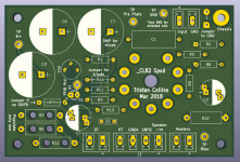
Thanks - yep, should have added that. Attached is an updated set. Added an additional pad to make the -ve connection to the OT / speaker connector.
I'll need to review the grounding - I had hoped to keep GND as the pour and GNDA as short connections to each filter cap...
Attachments
All I can think of, adapt the circuit for cathode feedback, maybe then you can use a more common 5 k OPT for EL84.
All I can think of, adapt the circuit for cathode feedback, maybe then you can use a more common 5 k OPT for EL84.
Is that to the power tube from the +ve speaker?
The OPTs I have are all taken from old tape players I think. They measure ~6k averaged over a range of frequencies. I'll start with them, and if it sounds terrible can always move to a pair of Hammonds, e.g.
I'm not expecting stellar performance - just a fun exercise!
Is the heater really 16VDC ?
Watch for import duties with PCBWAY.
I bought 2 lots of $5 pcb's and paid £21 import duty.
Apparently when calculating import duty they add in cost of postage.
Watch for import duties with PCBWAY.
I bought 2 lots of $5 pcb's and paid £21 import duty.
Apparently when calculating import duty they add in cost of postage.
Last edited:
Is the heater really 16VDC ?
I was going by: http://www.r-type.org/pdfs/pcl82.pdf
With 16V my measured curves look very close to those ones too.
Watch for import duties with PCBWAY.
I bought 2 lots of $5 pcb's and paid £21 import duty.
Apparently when calculating import duty they add in cost of postage.
Yeah - there's a sting, but still way cheaper and faster than anything in the UK for the cost. I'll likely order a few other things at the same time to offset the shipping.
I was surprised at such a high heater voltage but it is correct.
Maybe they have done a 12ax7 and put them in series.
Maybe they have done a 12ax7 and put them in series.
Not sure what "done a 12AX7" is, but TV valves such as the PCL82 were all designed for a 300mA series heater chain (in TV's the chain was fed via a large dropper resistor). As a consequence, the voltages the various types run from can be very wide ranging - from a few volts to over fifty in some cases. That's one of the reasons that they tend to be cheaper than their 6.3 VAC equivalents. But if you've got the supply available from a handy transformer they're often an option worth looking at.Maybe they have done a 12ax7 and put them in series.
I was surprised at such a high heater voltage but it is correct.....
Tube heaters are like lamps. They can be made in a wide range of voltage. Tube heaters run from 1.2V to 117V, at least, to suit the convenience of the system.
The really-high voltages are awkward. As 12E1 says, when the cheap power source is a high voltage such as line-voltage, you put heaters in series. (This also reduces wiring.) Then they must all be the same current: 150mA in US 5-toob radios, 300mA in TV sets. You got big tubes and little tubes of different heater-power needs. The big H-sweep tube may be 38V 300mA, the little tuner tube may be 4V 300mA. tristanc's tube is in-between and 16V seems reasonable. And its 6V brother, ECL82, is 6.3V 780mA. Same power (+/-2%) as PCL82. There is also UCL82 at 50V 100mA, and XCL82 at 8.2V 600mA.
The lesson is not so much "read the manual" as to look for alternates which are often half the cost of 6V and 12V tubes at the cost of an odd heater voltage. Tubes in the series-string TV series, the 6V jobs may be super rare while millions were made odd-voltage for low-price TV sets.
That was my first ever valve project back in the late 1970s, with a UY85 rectifier and simple dropper. Direct mains connection is not allowed now, thank goodness, but I learned a lot back then from building it.There is also UCL82 at 50V 100mA,...
[Sorry for the OT post.]
This talk of the heater voltages brings up something I’m not sure of:
I had planned to run the two valves’ heaters in parallel from a 16VDC regulated supply.
Is this OK, or do they need to be in series from a 32V supply?
Tristan
I had planned to run the two valves’ heaters in parallel from a 16VDC regulated supply.
Is this OK, or do they need to be in series from a 32V supply?
Tristan
PRR is right. The tubes are independent. So long as your 16 VAC supply can handle 600 ma (0.6 amp), you're in business. In fact it scales: use as many channels as you like. 'n' say. Current supply for heaters is n × 300 ma.
GoatGuy
GoatGuy
That was my first ever valve project back in the late 1970s, with a UY85 rectifier and simple dropper. Direct mains connection is not allowed now, thank goodness, but I learned a lot back then from building it.
[Sorry for the OT post.]
Its kind of sad that The Management so vociferously quashes designs that have direct-mains connections for some parts of circuits. Its not like they're intrinsically dangerous so long as there is an isolation transformer somewhere in the design. But perhaps the subtlety is lost on many readers. Ah well…
The professionals who designed color TV sets in the 1960s and 1970s certainly had the chops to know how to both safely design mains-connected tube kit and keep a handle on ground loops and other baddies that gremlin such systems. After all, the TVs worked. Pretty well, actually, considering how squishy analogue is at 55 MHz.
GoatGuy
Thanks both.PRR is right. The tubes are independent. So long as your 16 VAC supply can handle 600 ma (0.6 amp), you're in business.
I’ll need to redo the maths on the regulator & heatsink, but think things will be OK. I’ve an 18VAC tap and 275-0-275 HT and both over-spec for this build. In fact, the power supply will be completely over-spec’d for the expected fidelity!
So seriously... incorporate modern tech too...
Well then, here's what I would do. Build 4 units.
And purchase 1 ea. of the Alesis RA–100 or RA–150 amp on the used market.
They're like $50 ea. (I've used over a dozen of them, they're bomb-proof).
TRI-AMP your speakers. Build an active 3 way parametric crossover to sit in 'front' of the 4 cards and the L+R channels of the RA–100. Send BASS to RA–100. Send bandpass (mid) and high-pass (treble) to your 4 cards. Use cost-effective larger-gauge stranded wire to get from all outputs to each speaker. Rewire the 3-way speakers to bypass any internal cross-over. Direct drive each driver.
The beauty is, you can adjust the crossover frequencies. You can adjust relative gain of each too… in case the mid is too strident, etc. Quite different from an ancient 'tone circuit'.
The extra beauty is that you put the money where the performance is going to result. There is almost no point in having valves go all the way down to 18 Hz, since they're so expensive to do that adequately. Yet, the RA–100 does it trivially. Cheaply. With protection and all the rest. Your boards on the other hand do what tubes do best - the mids and the highs. You get 4× the power per channel or more (with the RA making up over ½ to ⅔ of it) potentially.
And the relatively high output distortion of the PCL–82 valve is band limited; you don't need to drive each one so hard, the harmonic distortion will be less.
That's what I would do.
As I've been doing now for a decade or so.
I like the results.
And I like “leading edge techy with steampunk underpinnings”.
Just me,
GoatGuy
Ha, now there’s a project! This started as something to replace my kitchen DAB radio and use a PT I have left over... And now I’m looking at making a foam board mini Karlsonator.
I need to stop reading these forums! ;-)
I need to stop reading these forums! ;-)
Or… just make the 4 boards, and plan on using them! You could use them to drive a second set of independent speakers. You could try "bi-amping" without the RA–100. Its a valid and downright impressive exercise (especially if you do only one speaker and leave the other untouched for a trivial A/B test live.)
And still hunt down a RA–100 to play with. Maybe $50 (originally it was $500+ retail...) is out of your range, but then … to me … so is competent valve retroengineering. LOL.
GoatGuy
And still hunt down a RA–100 to play with. Maybe $50 (originally it was $500+ retail...) is out of your range, but then … to me … so is competent valve retroengineering. LOL.
GoatGuy
You could add the option for plate-to-cathode feedback in case you want to play with that? (i.e. ring of two)
- Home
- Amplifiers
- Tubes / Valves
- PCL82/ECL82 SE PCB design - thoughts?