I have been using Jeff Bagby's PCD spreadsheet and have a question that I am hoping someone will be able to answer -
Is it possible to model a Woofer Tank filter in PCD i.e. Capacitor and Resistor in series both in parallel with the woofer series inductor in the low pass filter.
I can model this in Vituix and it deals well with a woofer break up around 3khz with a .2uF cap and 18ohm resistor but can't find a way to model this in PCD.
All help welcome.
No, unfortunately that's one of the features it always lacked. That apart, it can model the majority of common practical configurations within the pre-set topology options. WinPCD, which is based on PCD, can model tank circuits however. Despite the rise of VituixCAD, which is astonishingly capable, PCD remains my 'default'; I've used it for years & only shift to Vituix or LspCAD when I've got a different topology it can't handle (rare in practice) or I start working with & displaying off-axis in real-time, which I tend to do after establishing the basics.
Last edited:
Many thanks @Scottmoose for confirming my suspicions and that I am not just incompetent 🙂
In Vituix the tank does not make a huge difference to the frequency or phase so not a big issue in this case.
I have been bouncing between Vituix, Boxsim 2.0 and PCD and they all have their strengths. However, Boxsim is good for big picture stuff and getting close and doe the enclosure model well, Vituix is good for real-time rapid visualisation but I think PCD get you closes to real performance which shows when you re-model existing designs as a test.
Definitely not incompetence. Or if it is -at least it's a shared one. 😉 As I say, I still rate it. The consistency has always been excellent to measured results, so I usually stick with it (while acknowledging the merits & use of several other software packages).
One point, and purely for what it's worth (not a lot) -I don't know exactly what you're doing & what the drivers are, but especially if it's a metal cone -watch the HD lower down with the 3KHz breakup. You'll likely have a spike in HD2 @ 1.5KHz, HD3 at 1KHz & so on & so forth, although whether it's especially visible will depend on the baseline performance -ditto for audibility. I sometimes use tank notches for a bit of mild stopband response shaping, but usually not for a significant breakup mode, as they're rarely sufficient to hammer it out of the way / break circuit & significantly reduce distortion amplification. Opinions differ on this particular subject and its significance or lack thereof; that's my take, but YMMV as always.
One point, and purely for what it's worth (not a lot) -I don't know exactly what you're doing & what the drivers are, but especially if it's a metal cone -watch the HD lower down with the 3KHz breakup. You'll likely have a spike in HD2 @ 1.5KHz, HD3 at 1KHz & so on & so forth, although whether it's especially visible will depend on the baseline performance -ditto for audibility. I sometimes use tank notches for a bit of mild stopband response shaping, but usually not for a significant breakup mode, as they're rarely sufficient to hammer it out of the way / break circuit & significantly reduce distortion amplification. Opinions differ on this particular subject and its significance or lack thereof; that's my take, but YMMV as always.
Last edited:
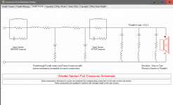
WinPCD has 2 Tank filters available for use ( either before and/or after the low pass components ) >< ( comprising; L1,C1+R1 or L4, C4, R6 ).
You might want to also look at switching away from Jeff's PCD to DLR's WinPCD ( which is based on Jeffs PCD ) but runs on Windows natively ( not needing Excel ).
WinPCD shows all the circuits ( + layouts ) available to the user once you click on the area that I've high-lighted ( in yellow ) .

Jeff's might wel have the same "parts" window ( but I don't know since PCD is not on this computer ) .
🙂
You might want to also look at switching away from Jeff's PCD to DLR's WinPCD ( which is based on Jeffs PCD ) but runs on Windows natively ( not needing Excel ).
WinPCD shows all the circuits ( + layouts ) available to the user once you click on the area that I've high-lighted ( in yellow ) .
Jeff's might wel have the same "parts" window ( but I don't know since PCD is not on this computer ) .
🙂
Attachments

Last edited:
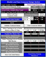
Try this:
Set your series inductor to "0" but include the series resistance of the inductor.
Then add in a Parallel RLC Notch Filter before the xo. Set the inductor value equal to your series inductor. Set the capacitor value equal to your parallel capacitor and set the value of the non-existent parallel resistor at something very large like 999999 which will essentially remove it from the circuit.
It should look something like the attachment below.
Note however that PCD can put the cap in there but it can't put that pesky series resistor into the equation. But that resistor doesn't change the location of the notch - it just diminishes its depth depending the value you choose. So if you really want to see the whole effect, then a different piece of software is going to be required.
Attachments
Right, you can do a parallel LCR, and you can do a bottomless LC in PCD7 (and 8) but alas, not a tank circuit with a series R and cap shunting an inductor. As noted, WinPCD does have that facility though once you navigate which resistor is which in the interface. 😉
Attachments
Last edited:
Many thank everyone for the info, will see if I can download WinPCD and have a play.
For info the application is a 3way using the SB WO24P-4, Morel EM1308 and Wavecor TW22WA09. Crossovers at 600hz and 3.4khz, Woofer and tweeter electrical 2nd order and Mid electrical 1st order which make all LR2 second order acoustic. Woofer in a 35l closed Monkey Coffin style box (360mm x 560mm baffle). This models up really nice with pretty much overlaid phase, slight 3-5dB slope from low to high (or can make it flat) and great directionality.
Troes does not use a tank in his SBA941 (crossed at 600hz) but does in his SBA761 and Jeff Bagby uses one in his Helios (crossed at 1.3khz), so I may not actually need one but it probably wouldn’t hurt to pay it some attention.
- Home
- Loudspeakers
- Multi-Way
- PCD question