Can anyone help me to get Pcbs etched from .pdf? I need about 4 3" x 4" PCBs and have the .pdf etch resist to scale. Thanks
I don't know of any commercial printed wiring board (PWB) fabricators that will work from *.PDF files. As you implied, the scaling and resolution isn't guaranteed to be tight enough for modern component sizes. (I think the underlying Postscript language actually COULD be a viable PWB description language, but I think the process of converting and compressing to *.PDF compromises the capability unless the *.PS code was written with specific attributes to preserve resolution and accuracy. I don't recall ever seeing Postscript used that way.)
If you are working with thru-hole parts and have adequate trace width and spacing, and a printer that is free from geometrical distortion, you can probably make PWB's at home using your *.PDF files and, e.g., "toner transfer" or similar methods. You may find tutorials or other help in the Yahoo "Homebrew_PCBs" group at I don't know of any commercial printed wiring board (PWB) fabricators that will work from *.PDF files. As you implied, the scaling and resolution isn't guaranteed to be tight enough for modern component sizes. (I think the underlying Postscript language actually COULD be a viable PWB description language, but I think the process of converting and compressing to *.PDF compromises the capability unless the *.PS code was written with specific attributes to preserve resolution and accuracy. I don't recall ever seeing Postscript used that way.)
If you are working with thru-hole parts and have adequate trace width and spacing, and a printer that is free from geometrical distortion, you can probably make PWB's at home using your *.PDF files and, e.g., "toner transfer" or similar methods. You may find tutorials or other help in the Yahoo "Homebrew_PCBs" group at http://tech.groups.yahoo.com/group/Homebrew_PCBs/ . Also look at the thread " Dirt cheap prototype PCB manufactory" at http://www.diyaudio.com/forums/class-d/228190-dirt-cheap-prototype-pcb-manufactory.html
Dale
http://tech.groups.yahoo.com/group/Homebrew_PCBs/
As long as your scaling is trustworthy, you may be able to by with a tool such as pdftogerb
link below
pdf2gerb: Convert PDF to Gerber and NC Drill formats
Consider my post a reference for the direction in which you need to look, rather than a "be all, end all" solution. I used it once in it's infancy to covert a scan from an old electronics magazine with acceptable results - but that was some time ago... now I just redraw the schematics from scratch, then import the netlist into a PCB program, then redraw the boards from scratch - to my liking, with footprints for the parts of my choosing.
I'm sure that there are other suitable tools out there as well.
My reasoning behind redrawing the entire project from scratch, is to expose flaws in the original design, along with opening the window to beneficial improvements. All too often, I come across "plans on the internet", that when rationally dissected, and analyzed one part at a time (especially by a community such as this), important design issues are exposed, long before copper is etched and iron is laid to solder.
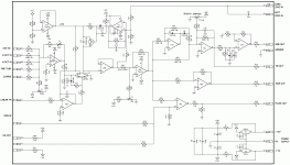
Your schematic image isn't very legible. Can you grab a full-resolution JPEG image and attach it to a post? Or post a link to the web page with the original image? This looks like a function generator project - is there an '8038 or '2206 in there someplace?
I am not familiar with ExpressPCB's online layout program, though I know that several PWB fab houses have similar programs. Which "objects" are giving you problems? I have laid out at least a dozen PWB's using (expensive!) commercial programs, and it's not unusual to spend a significant amount of time - perhaps 1/4 or 1/3 of the total effort - doing "library" work such as creating symbols, editing footprints, etc.
Dale
1) the schematic is legible, you just need an extra Zoom step. 🙂
First click on the image for a larger preview, then click on the expansion arrows which appear bottom left.
Or open the image in another window.
2) it's a "discrete" function generator designed around generic ICs, not dedicated ones such as you mention.
3) the Op amps should be no trouble, they are DIP8 or DIP14, available on Express PCB
Don't remember the pinout of LM394, but just check the Datasheet 😉
4) I sometimes use or recommend Express PCB because it's quite straightforward.
It's meant to be sent to them for fabrication (reasonable prices anyway) but for prototyping, you can export the PCB traces as a .bmp which can be laser printed for thermal transfer or Photo Sensitive PCB (killer definition, looks real Pro)
For posting on Forums, first convert bulky .BMP into monochrome .gif or .png .
Avoid .jpg like the plague it is.
5) as suggested by Dale above, *if* you have a part which is not in the library (not the case here), you can draw it yourself and add it.
You are correct - I wasn't familiar with that 4-way arrow symbol (reminds me of the graphic logo used to identify 1970-vintage "quadraphonic" audio technology).1) the schematic is legible, you just need an extra Zoom step. 🙂
First click on the image for a larger preview, then click on the expansion arrows which appear bottom left.
I believe the LM394 is obsolete and out of production. THAT Corp and Analog Devices are still making matched transistor pairs intended for audio applications but I don't know if the packaging and pinouts are the same as the LM394.Don't remember the pinout of LM394, but just check the Datasheet 😉
Dale
True enough, but "modern equivalent" will probably still be packaged into something standard, they want people to use it after all, so they must make it easy for designers.I believe the LM394 is obsolete and out of production. THAT Corp and Analog Devices are still making matched transistor pairs intended for audio applications but I don't know if the packaging and pinouts are the same as the LM394.
Wirst case, you can use 2 regular (matched) TO92 transistors , mounted flat side to flat side, with a small drop of thermal grease between them and neatly tied with a couple turns of bare copper wire.
I used that improvised replacement in analog synthesizers LONG ago (don't ask 🙁 ) with good results.
They were as hard to keep in tune as the original LM394, but not worse. 😱
I have decided to try to go the expresspcb route. I am however encountering difficulty with objects. Mostly with the ICs. This is a schematic of a DIY Oscillator
I like 🙂
not balanced output ? 😡.....🙂
Dear argon republic, re-reading your first post , it looks like you *already* have the PCB trace in that .pdf .
Is that so?
If so, please post it here so we can see it and give you an opinion.
Some PCB designs are "doable at home", some are a nightmare best left to fabricators.
Maybe you can work with what you already have.
Is that so?
If so, please post it here so we can see it and give you an opinion.
Some PCB designs are "doable at home", some are a nightmare best left to fabricators.
Maybe you can work with what you already have.
I have decided to try to go the expresspcb route. I am however encountering difficulty with objects. Mostly with the ICs. This is a schematic of a DIY Oscillator
Fahey in this posted diagram i would try to mix/sum the output of u7d and u6c...😀😀😀
I use Pad2pad and am a happy customer.
Pad2Pad - Custom Printed Circuit Board Manufacturer | General | Main
Designing a PCB is not simple, but it's not rocket science either.
4"x3" is pretty small.
Pad2Pad - Custom Printed Circuit Board Manufacturer | General | Main
Designing a PCB is not simple, but it's not rocket science either.
4"x3" is pretty small.
Ther problem was in the transistors symbols. Following some time spent staring at it, I concluded that a pair of tranistors symbols represented an OPA2137, I am guessing from this point that U7a, b, c and d are a combination of transistors that make up the TL074. The source of oscillation is thr transistor pair which is an LM394. I could be wrong, I have never attempted a project like this.
I have a .pdf that I could print and etch. I have never etched a board either. I don't have the equipment on hand and felt that I could become active by redoing the schematic while learning the software. When and IF I am successful, I could upload and get pcbs. Either direction is going to require some effort and possible loss.
The circuit is a Voltage controlled oscillator for modular synthesizer.
- Status
- Not open for further replies.
- Home
- Design & Build
- Software Tools
- PCBs from.pdf