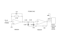
I've been trying to draw the schematic for a chi-fi PCM56 DAC I have. This is my best shot. Does it look correct?
There seems to be some sort of Omron relay on the output but I can't find 1 BY3 N1. May be 18Y3 N1
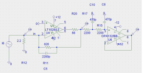
I also attach the schematic for a LT1028 output. Does this look better?
There seems to be some sort of Omron relay on the output but I can't find 1 BY3 N1. May be 18Y3 N1
I also attach the schematic for a LT1028 output. Does this look better?
Attachments
With one PCM56 only in the first shematic I will use Rfb : 2700R and Cfb 1nF (COG or acrylic). You can use the input filter of Rutgers shematic 2 with R12 and a C0G cap between ground and R12 as per the shematic. Perhaps op1641 instead the op134.
It is important to make loop area of the feedback littliest you can : use smd parts here; 1206 resitors and 0805 caps close to the opa amp and input pins are okay with magnify glasses.
It is important to make loop area of the feedback littliest you can : use smd parts here; 1206 resitors and 0805 caps close to the opa amp and input pins are okay with magnify glasses.
Last edited:
My schematic is number two in the list - not the LT1028 one. You suggest changing 4.7K feedback resistor to 2.7K with same 1nF? How does that change the gain of the stage - what's the formula?
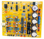
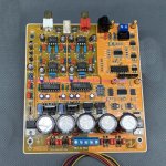
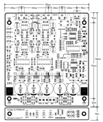
I can't do surface mount, just leaded components. But the board is already built, as you can see in the photos. What I want to know most is does my schematic look correct? Does it make sense or might I have got any connections wrong? And what's the relay and what does it do - is it necessary?
I can't do surface mount, just leaded components. But the board is already built, as you can see in the photos. What I want to know most is does my schematic look correct? Does it make sense or might I have got any connections wrong? And what's the relay and what does it do - is it necessary?
Nope I talked about shematic one of your post. I won't discuss the NE5532 chi-fi shematic. I assume you want to improve it
The // Cf & Rf is a simple 6dB slope filter. Rf gives the gain. Too much adds noise. ouput I from the DAC x R from the Rfb = V output.
Use what you have at hands with THT if smd is not possible,, but at least a good MKP cap with the pitch of the axial resitor rigth on it with shortest leads length you can solder.
The relay is possibly an antipop delay or the choice between SE and symetric, what day the merchant ?
But I don't loose too much time on so cheap pcbs because most of the time the goal is too stay cheap not to focus on sound quality. 4k7 as Rfb seems to me too strong value, you have a pre, rigth ? Try 1k to 2K7. (3k3 gives you the classic 2V with 1MA output) Target the filter for something grossly >100 Khz.
The first shematic you linked is from Rutgers and you have all the informations : I regave you the link I gave : https://www.by-rutgers.nl/IV-converter.html. Hard to find a better didactic paper imho. Have you read the datasheet of the PM56 as well as advised ?
Last edited:
Iggy - I'm not going to rebuild the chi-fi board. I might possibly make small changes but that's all. I just wanted to understand the circuit and see if my schematic is correct. I'm new to DAC theory. This applies in particular to the second NE5534 connections. I haven't connected it all up yet but I presume it works. I might try some different op-amps. I have LT1028, LT1362 and one or two more.
I have 2 of these boards. I can use the other one for a valve output off pin 13 of the PCM56 and bypass the op-amps completely.
I have 2 of these boards. I can use the other one for a valve output off pin 13 of the PCM56 and bypass the op-amps completely.
I've been playing around with some of the cheap PCM56 mini DAC boards in post #16. I'm using my ECC40 valve stage as output via a 220R I/V resistor. Apart from some low level hum which I need to track down, this is the best sound I've achieved so far. Smooth, detailed, and good tonality on acoustic instruments. You need to snip pin 9 on the PCM56 to use the current output.
I've also got the larger PCM56 board working, shown in post #21. It has a thin detachable board with a selector switch on it and this needs to be connected via the lead provided for the board to work. Since the chips are socketed I swapped in a pair of AD1856 and that seemed an improvement, but not night and day. Next I swapped in a pair of LT1028 for the NE5534s in the first op-amp stage. These were not happy - edgy treble. So they came out and were replaced with a pair of LT1363, which seem to work well. With these changes the sound is quite pleasant and I'll leave it like this and do some listening. I've left the NE5534s in the second op-amp stage.
Any suggestions for the op-amps in the first and second stages? DIL8 sockets. Schematic in post #21. I have pairs of AD845, OP37 and OP27 and various NE5534s. Old stock. I could put some SOIC chips on adapters if necessary.
I've now been listening to the PCM56 board on AliExpress for a while (post #21) and it's been a good starter project into the world of multi-bit DACs. The main chips are socketed so useful for modifications. It comes with 2 stages of NE5534 and there are various ways of altering that. What I have right now is AD845 in stage 1 which is a nice sounding op-amp. I removed the small cap between pins 5 and 8 that is used for the NE5534. I then wanted to try using just one I/V stage without the buffer, so I took the output direct from pin 3 on stage 2. This is the current setup.
I attach the schematic for the I/V stage. I'm sure the filtering isn't ideal so I may look at that next. The PCB isn't good for changing parts, though - the solder tags are tiny and the parts are close together. Still, for a starter project it gets you up and running quickly and cheaply. PCM56 chips are available and cheap, plus AD1856 is an option. The case I used was Hammond 1550J, 275x175x67mm. I used 15+15V 15VA and 9V 8VA transformers. There's a thin board with a selector switch which needs to be fitted via a cable, and this was set to SPDIF input
I'd be interested to hear from anyone else who has experimented with this board.
Last edited:

Going back to the start of the thread where it's mentioned PCM63s are getting expensive .. they are found in so many cheap and being thrown away pieces of equipment that they are still cheap. Maybe the desoldering is an issue though ?
Pro market is the best, but may require a little research and experimentation with old digital gear to see what chips they do use. Something like a late 90s Pro Tools 888 interface for £30, or a Yamaha 8 channel D/A designed for a specific early Yamaha digital desk, old broadcast cart players who's mechanisms are broken .. that kind of thing.. Broken FireWire audio interfaces .
I assume the main issue is one of information - what exactly is inside each unit. One normally only finds out by buying it (only to find it's a Crystal 48xx or whatever the number is .. lol )
- Home
- Source & Line
- Digital Line Level
- PCBs and built boards for PCM56 or AD1865