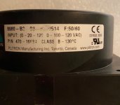
I bought two very nice Plitron PCB transformers on eBay, model 8980-B2, 0-20-120V and 0-100-120V inputs, 50/60Hz, 2 X 18V output at 0.56A and 1X10V output at 0.43A. I thought I might design a PCB to use them. But it's unlikely I will ever get around to learning PCB design and doing it.
So here's my proposition: you get one transformer in exchange for designing and ordering two PCBs, then you send one PCB back to me.
So here's my proposition: you get one transformer in exchange for designing and ordering two PCBs, then you send one PCB back to me.
Attachments
Design a pcb to rectify / smooth AC for a DC Power supply? Why redesign the wheel - I have a ton of them, and can be bought off ebay cheap too......
If not a power supply PCB, what is your PCB is to be doing...
Piltron makes some very nice (and expensive) transformers...
If not a power supply PCB, what is your PCB is to be doing...
Piltron makes some very nice (and expensive) transformers...
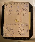
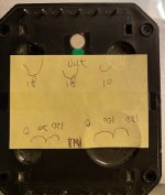
Ah, I should be more specific. The transformer is does not have the same pinout/spacing as a typical (ie Talema or flathead) transformer. I could not find a PCB that it fits. I could not find a protoboard that it fits, although there probably is one somewhere.
So what I'd like, at the minimum, is a PCB that mounts just the transformer with pads for the pins that input and output wires can attach. I would like it if the pads can attach to screw on terminal blocks or similar.
But this is a collaboration. If someone wants to take me up on this project and design something with rectifiers and filter caps, I can work with that.
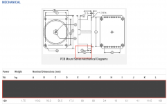
Have you confirmed with a ruler that the 120va specs reflect the correct mechanical drawing? This model does not appear to be a standard offering for their current PCB series. Can you also confirm the actual measurement of dimension K and the individual lead spacings for the primary and secondary pins? If you can, I’ll take a crack at a PCB.