Hi, its time for the second part of the mini-series covering PCB layouts.
The subject is clock distribution and signal integrity. The background is that there are often simple solutions that I often miss when reviewing designs. Solutions that do not cost and are simple.
Nice reading on Regal technology. Looking forward to your comments!
Take care,
Anders
The subject is clock distribution and signal integrity. The background is that there are often simple solutions that I often miss when reviewing designs. Solutions that do not cost and are simple.
Nice reading on Regal technology. Looking forward to your comments!
Take care,
Anders
A 47 Ohm is not always the best choice.. It depends on the layout, the drive strength of the driving gate, the ability of the receiving gate to sink current etc. I would again recommend providing some further links for reading....
Real world examples...
Real world examples...
Attachments


This is the list of links I provide when asked on other forums about starting PCB design PCB Related Links.txt (I am currently updating this as it was done rather quickly originally).
The other files are other PCB related links and a list of documentation in one of my PCB folders that you may find useful.....
The other files are other PCB related links and a list of documentation in one of my PCB folders that you may find useful.....
Attachments
I agree, but 47 ohm is a good starting point if you don't do any board optimization. But if you want to optimize the damping resistor, it should be tuned with respect to driver impedance, the clock signal impedance etc. As with any subject, its possible to dig deeper into further details and optimization.
Nothing is like real world examples!
My point in the blog is to adress some critical design issues that are simple to solve. And also to show the effectiveness by relevant, simulation results. In most cases simple solutions and simple models are good enough if implemented correctly.
Nothing is like real world examples!
My point in the blog is to adress some critical design issues that are simple to solve. And also to show the effectiveness by relevant, simulation results. In most cases simple solutions and simple models are good enough if implemented correctly.
Thanks a lot for the links! I will add links to my blogs for all guys that want to read more.
I have read some of the referred papers, but some are new to me. As my primary interest is within audio design, I know Bruno Putzey has written some good stuff as well. If guess you are familiar with him as well...
I have read some of the referred papers, but some are new to me. As my primary interest is within audio design, I know Bruno Putzey has written some good stuff as well. If guess you are familiar with him as well...
Mostly true, but a couple of caveats...
2: these days due to board complexity, signal integrity EMC, thermal etc, a prototype is as near the finished product as possible otherwise a lot of the testing is often pointless. If an engineer is unsure about a circuit module, they are sometimes done as a simpler cheaper board just to test that modules function. Its a cost and turn around issue as well...
6: Libraries are critical, anyone creating a sub-standard library is a muppet, they must be correct
8: Don't know any designers that use autorouters and I know a lot.
The final comment by SpatialKing I found worrying in this day and age, for SMD footprints you should always use the IPC-7351 standard
and of course Altium (nee Protel) is the most horrid heap ever, but profitable if you can be bothered to work it out (most fail). 🙂
Personally having used all the major systems, AI don't like Altium, it is Protel with a fancy coat hiding the horrendous interface underneath... Out of all the main systems it generates the most "how to" questions on PCB based forums. It is not that cheap when you look at it from a standard engineering dept point of view, the average is about 4-6 schematics to one layout, so a single user (1 schematic/ 1 layout) looks OK price wise, but once you get to departmental usage the price due to the cost of the schematic package is the same or more than many other systems.
If anyone is wondering the basic programs are:-
Orcad PCB editor (Cut down Allegro): Cadence
Cadstar: Zuken
Pads: Mentor Graphics
Altium: Altium
The top flight packages are:
Allgero: Cadence
CR8000: Zuken
Boardstation: Mentor
Then there are the hobby minimalist packages, the most famous being Eagle, the rest being generally free from the likes of RS etc (KIcad etc.).
I have not done professional pcb design for 15 years now, but many things remain somewhat the same.
I still do pcb design at home however, using orcad16 layout. never had a need yet to use orcad pcb designer(Allegro). I dd use Allegro way back in the 90's.
I was playing around with diptrace, it is not so bad for small stuff.
Mentor Xpedition® Enterprise is the old Veribest/Cadnetix. I had lots of experience with Boardstation, but got out of pro pcb design just when Mentor bought veribest.
Boardstation was abandoned for Veribest technology back in the early 2000's.
Have you ever tried it? It is part of Cadence Allegro now.
I still do pcb design at home however, using orcad16 layout. never had a need yet to use orcad pcb designer(Allegro). I dd use Allegro way back in the 90's.
I was playing around with diptrace, it is not so bad for small stuff.
Mentor Xpedition® Enterprise is the old Veribest/Cadnetix. I had lots of experience with Boardstation, but got out of pro pcb design just when Mentor bought veribest.
Boardstation was abandoned for Veribest technology back in the early 2000's.
I am one who used a autorouter, quite a bit actually, it was originally the CCT Specctra SP55 shape based auto-router. I rememeber it cost $50K US back then. To make it tick, you had to setup a proper do file, or your results were not so great.Don't know any designers that use autorouters and I know a lot.
Have you ever tried it? It is part of Cadence Allegro now.
Last edited:
I used autorouters in the mid 80's up to mid 90's, mainly what was then Racals Visula router, Preditor. As SMD footprints got more complex though using a autorouter as we used to use them has diminished. Now on more complex digital designs with BGAs I use the interactive routing tools, so its not so much autorouting, more manual routing with auto-tools. BGA breakout is a prime example, a few seconds using the auto functions to create the desired fan out.
Diff pair routing is another.
I have used autorouting in very selected areas, with many restrictions, such as very limited layers, its so dependant on layout, PC motherboards using southbridge interface devices are a good example of an "autoroutable" design: A FPGA with two two DDR memory chips (not a module) etc. are generally best done manual (with interactive help, for length matching etc.).
Talking of length matching, I find it best when routing to separate DDR IC's, manual is best as you can leave more room around tracks you know are going to need a lot of serpentine length matching. Nothing beats experience for these interfaces, the first time I did a DDR interface I was anxious, did a couple of courses on all aspects on the interface and had my design checked and simulated. Now many years later, there have become the norm, with many designs now using DDR memory.
I used Allegro for several years, and enjoyed many aspects of it, and have used Spectra in the past, setup was everything and became so time consuming in some instances... but that is the same with any autorouter, a design done manually is done in a certain sequence, but changes in that sequence are possible because of the way we work. Autorouters have to work in a rigidly defined sequence, they cant stop one routine because of a minor issue (e.g. a component needs moving a small amount) so have to keep going working round the obstruction, leading to sub optimal routing and thus requiring manual intervention to clean the design up. This is more prevalent today due to the component footprints and circuit density.
Analogue I always manually route.
Most power distribution involves copper pours, so again this is a manual operation, drawing the templates for copper pours.
You have lots of pcb design experience marce. Very few folks in this forum have pcb design experience.
You are correct in that you do use an auto-router but for specific nets and tasks such as fan outs, length matching, DRC/DFM checking.
Having to manually match the lengths of bundle(32-bits) is very time consuming to say the least.
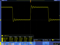
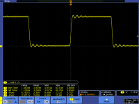
The subject is clock distribution and signal integrity.
I can add from my experience what we did back then and is still valid today.
You were talking of one type of transmission line termination, which is defined as source series termination. The incident wave is generated at the source and is reflected back. The incident wave is doubled up at the end termination (high Z or open T/L) and reflected back to the source. The idea is the combination of the source termination and driver Z is to damp the wave to minimize the reflection back to the load. The choice of termination R depends on the trace impedance and the driver's Z.
Back in the day and still valid today, we used Hyperlynx SI initially to model the transmission line to chose the termination R. To do so, you need a IBIS model of the driving and receiving devices. Most IC suppliers supply these models for free.
Hyperlynx was bought up by Mentor Graphics in the early 2000's. It is an excellent tool to use, by itself.
https://www.mentor.com/pcb/hyperlynx/
When we were using high end Vitrex Xilinx FPGAs, they had an o/p cell option to include the source series termination in the driver. It was an nice feature to use, as it saved lots of pcb real estate.
Another s/w package that we used and that was also bought up by Mentor was Interconnectix.
Mentor Graphics Corporation acquired Interconnectix Inc. in 1996.
Cadence has their SigNoise tool that does the same thing.
These s/w packages did SI analysis of your finished/routed pcb where it used IBIS models and pcb parasitic's to model your transmission lines.
One good reference on transmission line work is the old Motorola MECL system design handbook
d3i5bpxkxvwmz.cloudfront.net/pl/1276642244-MECL-system-design-handbook.pdf
In those days TTL/CMOS edge rates were so slow that it did not matter much, but for ecl it was important.
Now CMOS edge rates are much faster, so this information applies to it.
Enough about transmission line work, this is an audio forum and the majority does not apply.
You are correct in that you do use an auto-router but for specific nets and tasks such as fan outs, length matching, DRC/DFM checking.
Having to manually match the lengths of bundle(32-bits) is very time consuming to say the least.
The subject is clock distribution and signal integrity.
I can add from my experience what we did back then and is still valid today.
You were talking of one type of transmission line termination, which is defined as source series termination. The incident wave is generated at the source and is reflected back. The incident wave is doubled up at the end termination (high Z or open T/L) and reflected back to the source. The idea is the combination of the source termination and driver Z is to damp the wave to minimize the reflection back to the load. The choice of termination R depends on the trace impedance and the driver's Z.
Back in the day and still valid today, we used Hyperlynx SI initially to model the transmission line to chose the termination R. To do so, you need a IBIS model of the driving and receiving devices. Most IC suppliers supply these models for free.
Hyperlynx was bought up by Mentor Graphics in the early 2000's. It is an excellent tool to use, by itself.
https://www.mentor.com/pcb/hyperlynx/
When we were using high end Vitrex Xilinx FPGAs, they had an o/p cell option to include the source series termination in the driver. It was an nice feature to use, as it saved lots of pcb real estate.
Another s/w package that we used and that was also bought up by Mentor was Interconnectix.
Mentor Graphics Corporation acquired Interconnectix Inc. in 1996.
Cadence has their SigNoise tool that does the same thing.
These s/w packages did SI analysis of your finished/routed pcb where it used IBIS models and pcb parasitic's to model your transmission lines.
One good reference on transmission line work is the old Motorola MECL system design handbook
d3i5bpxkxvwmz.cloudfront.net/pl/1276642244-MECL-system-design-handbook.pdf
In those days TTL/CMOS edge rates were so slow that it did not matter much, but for ecl it was important.
Now CMOS edge rates are much faster, so this information applies to it.
Enough about transmission line work, this is an audio forum and the majority does not apply.
Last edited:
- Status
- Not open for further replies.
- Home
- Design & Build
- Construction Tips
- PCB layout - tips & tricks part II