Hi Primoz
I have published something that may help you to measure the inductors:
http://www.diyaudio.com/forums/showthread.php?s=&threadid=77919
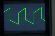
Also, your oscilloscope picture tells that either the probes or the oscilloscope (or both) don't have enough bandwidth to accurately show 300Khz waveforms and the switching glitches associated to class D circuits. The waveform should appear very square and probably with some overshoot, but never rounded.
Concerning the shutdown, I think that the problem was both related to the multi layer inductors drawing high current peaks on each transient due to capacitance, and to a lack of close enough supply decoupling, since these fast current spikes cause substantial voltage drop acros the leakage inductance of any PCB track. Anyway, spikes are not desirable so inductors with as little capacitance as possible should be employed (the best ones are single layer gapped ferrites or toroids, where wires doesn't even touch).
I have published something that may help you to measure the inductors:
http://www.diyaudio.com/forums/showthread.php?s=&threadid=77919
Also, your oscilloscope picture tells that either the probes or the oscilloscope (or both) don't have enough bandwidth to accurately show 300Khz waveforms and the switching glitches associated to class D circuits. The waveform should appear very square and probably with some overshoot, but never rounded.
Concerning the shutdown, I think that the problem was both related to the multi layer inductors drawing high current peaks on each transient due to capacitance, and to a lack of close enough supply decoupling, since these fast current spikes cause substantial voltage drop acros the leakage inductance of any PCB track. Anyway, spikes are not desirable so inductors with as little capacitance as possible should be employed (the best ones are single layer gapped ferrites or toroids, where wires doesn't even touch).
Today I had a lot of other work to do, so I will compare amplifiers tomorrow, because I don't want to wake up my neighbours now.
Eva:
My osciloscope is 10MHz. Last time something was wrong with my test equipment (maybe I didn't connect ground of osciloscope). Now I get something like that. It moves up and down with music.
Thanks for link, I will make this circuit as soon as I find enough time.
I'm at home only at weekends (school), so I couldn't reply before
Attachments
Sorry, last week I had a lot of other things to do.
I connected TDA8920 to speakers and I think it sounds good, much better then I expected but I didn't have time to compare with TDA1514A
I connected TDA8920 to speakers and I think it sounds good, much better then I expected but I didn't have time to compare with TDA1514A
I have a TDA8920 module in hand and noticed that the outputs are somehow in reverse, ie, one of the spkrs '+' will be connected to the SGND. I checked the datasheet and it seems that way.
Is there a reason why is it so? the block diagram seems to show 2 symmetrical circuits.
Is there a reason why is it so? the block diagram seems to show 2 symmetrical circuits.
This allows you to easily connect amplifier from stereo to mono bridge mode. Another reason is that this connection is more friendly to power supply. When both channels have similar input, both power rails are loaded almost equaly, so you need less capacitance in your power supply
Same connection you can find in car amplifiers
Same connection you can find in car amplifiers
problems with this ic
i have these ics and i made a temporay circuit to check the ic.
the stabi voltage is 2.5V instead of 12V and the voltage across one output is 30V and the other is 0V.
I used a conventional +/-30V power supply usin a transformer bridge rectifier circuit..
i made a circuit similar to that given in the datasheet. but when first connected the stabi voltage was 12V.when the stabi voltage was 12V i just touched the input wires but no sound came in the speaker.
i didn't connect any of the inputs.
can u help me solve this problem? Is there any chance of ic bein damaged of this issue?
hi, I am new here. I want to build amp with TDA8920Bj. Do you have final working board for this amp?? sorry for my english..🙄
BWRX said:So all this time it was just a supply decoupling issue... At least it was a simple fix!
Any opinion on how your implementation of the TDA8920 sounds?
i had make a pcb for 8920 2years ago
bass is great, but treble is too hard
also comparat with ta2022, pcb from trepath
same time, same speaker(tannoy), same power supply
ta2022 is poor bass, good treble
rg
fumac
Hi Primoz or anybody. Please could someone post here the finlal working PCB board for TDA 8902BJ(non-SMD).  Thanks
ThanksPcb Help
Hi i am new here and i was wondering if anyone cold post a list of components and pcb lay out for that TDA8920BJ
thankx
Hi i am new here and i was wondering if anyone cold post a list of components and pcb lay out for that TDA8920BJ
thankx
Look here for a version with TDA8920BJ amplifier PCBs.
I got it from a Vietnamese website. It is professionally designed but I am not 100% sure it works
I got it from a Vietnamese website. It is professionally designed but I am not 100% sure it works
Im using homemade switching power supply which has regulated both rails. Voltage is +/- 25V. I measured the voltages with load of 200W but they stay the same
I tried with standard supply (trafo, greatz, two capacitors) but the problem stays the same
At the picture is top view of finished PCB.
At left are air inductors, but I tried also with toroide inductors from old computer power supply, and with some other inductors, but problem was always the same
I built this amplifier. I have used the same PCB as in the case of @ Primoz.
What kind of heatsink did you use?
It is not clear even in the datasheet.
How do you mechanically mounted the heatsink?

Problem with my project
Hi guys,
I recently started doing tda 8920bj project. But its not working at all. I got inductors 47 micro henry small type. Can anyone help me out giving correct circuit and components.
Thanks,
Dileep m
Hi guys,
I recently started doing tda 8920bj project. But its not working at all. I got inductors 47 micro henry small type. Can anyone help me out giving correct circuit and components.
Thanks,
Dileep m
kiran bhandare
I have problems with my TDA8920BJ (non-smd version). At about 10W of output power overcurrent protection starts to work. I've tried almost everything except changing the PCB and I think this is the problem. I have designed single sided PCB and I had a lot of compromises to make (capacitors are not close enough to chip, output inductors are not shielded and are close to inputs...).
I would be very grateful if somebody could give me PCB layout which was tested and works, because I have spent too much time designing and making PCB-s, that dont work (5 pieces).
Layout can be double sided.
If anyone wants I can attach my layout if I can find it. Last time I was designing PCB was almost a year ago, then I gave up working with this IC-s and I started again this week
Thanks
- Status
- Not open for further replies.
- Home
- Amplifiers
- Class D
- PCB layout for TDA8920BJ wanted