hi. i have a suggestion...if u use the 3 x 1000uf (3000uf) on the rail for each side... you dont need to use the 2 x 220uf cap's used in the board....this caps suppose to use as the rails caps or am i wrong?
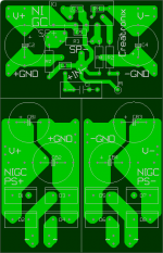
tip #2: your chip should be on the top of the board so dont add resistors behind the chip (18k res.) if you can, move it a little lower... , space is also important for the heat & for the heatsink that should be connected....the back of the chip can be the -Vcc on the metal plate, so i recommand lower the resistor also for the legs not to touch the heatsink....

tip #2: your chip should be on the top of the board so dont add resistors behind the chip (18k res.) if you can, move it a little lower... , space is also important for the heat & for the heatsink that should be connected....the back of the chip can be the -Vcc on the metal plate, so i recommand lower the resistor also for the legs not to touch the heatsink....
tip #3: on the PS buffer PCB join the 2 ground rails together...
you will have more comftarble to connect into the amp...
if you are planning a Pre-amp for this amplifier i sugguest you re-consider this PS buffer PCB, anyway for 6 CAPS you can use wires or test board, it will be expensive to make this PCB rather than connecting them into a Veriboard or with wires.
🙂
Is this for a standard power supply or a regulated?
I had assumed regulated due to the smaller caps on the chip board. 🙂 (though, 220uF is probably bigger than needed for that).
Otherwise, I know a lot of people don't like more than 1500uF (maybe 2000uF) per rail, and as close to the chip pins as you can get. Does stuff to the midrange and trebel output, though more capacitance can help bass response.
C
Upupa Epops said:For this output power use standard bridge such as KBUJ 8, which you can give directly to this PCB. Don't belive to anything who will say to you, that you need some exotic ones - it says only ones, who don't know design correct PCB. With bridge on PCB commonly with elyts you get shortly wires, which is more significant than any exotic bridge or diodes.
I would prefer diodes over a bridge because these diodes can be mounted against a heatsink, if I can add the diodes to the pcb then it will be OK too I guess?
The diodes would be standard types (I planned on using byv32.)
Morbid said:hi. i have a suggestion...if u use the 3 x 1000uf (3000uf) on the rail for each side... you dont need to use the 2 x 220uf cap's used in the board....this caps suppose to use as the rails caps or am i wrong?
tip #2: your chip should be on the top of the board so dont add resistors behind the chip (18k res.) if you can, move it a little lower... , space is also important for the heat & for the heatsink that should be connected....the back of the chip can be the -Vcc on the metal plate, so i recommand lower the resistor also for the legs not to touch the heatsink....
tip #3: on the PS buffer PCB join the 2 ground rails together...
you will have more comftarble to connect into the amp...
if you are planning a Pre-amp for this amplifier i sugguest you re-consider this PS buffer PCB, anyway for 6 CAPS you can use wires or test board, it will be expensive to make this PCB rather than connecting them into a Veriboard or with wires.
🙂
1: From what I understood the 220uF / 100nF combination should be there for bypassing and they should be kept near the IC. They will of course also do some buffering.
Since 220uF buffering is not enough I have added a separate pcb for the buffering caps.
2: The 18k resistor is a SMD device and will be soldered on the copper side of the pcb. I have reread the docs for the pcb shop and apparently there is only a need for 2mm space if the pcb is going to be panelized.
This is not the case in my case, so I can (and will) remove the area I have kept clear and the chip will be at the border 🙂
3: The grounds of the PS should also come together at the star ground.
That is the idea behind it, I have read it somewhere on this site.
Personally, I don't know if it will make a difference, but I guess it doesn't hurt to keep them separate upto the star ground.
I will join the 2 pcbs into one bigger pcb (which I will cut upon arrival.)
This doesn't increase the price too much (the main cost is in the initial setup), and it is a lot nicer to see.
cjd said:Is this for a standard power supply or a regulated?
I had assumed regulated due to the smaller caps on the chip board. 🙂 (though, 220uF is probably bigger than needed for that).
Otherwise, I know a lot of people don't like more than 1500uF (maybe 2000uF) per rail, and as close to the chip pins as you can get. Does stuff to the midrange and trebel output, though more capacitance can help bass response.
C
It is for a standard supply, each channel will have a 225W toroid transformer, byv32 diodes and 3000uF per rail.
I think that more capacitance is better, but I've read (again, I've read a lot lately) the problem with bigger capacities is that internal resistance is higher.
That is why I prefer 3 x 1000uF over 1 x 3300uF. And because these are separate devices I might try and use only 1 or 2 * 1000uF.
To squadra : I have used KBU 8 bridge in over than 500 pcs 100 W modules ( without heatsink ) with 100 % reliability. I think, that your fear is excessive.
Morbid said:tip #3: on the PS buffer PCB join the 2 ground rails together...
you will have more comftarble to connect into the amp...
[snip]
Sorry Morbid, but this is exactly the wrong thing to do! If you do that, any ripple, noise or distorted signal return current (don't forget this is class AB, so supply current is half-wave rectified) from one channel will cause an 'input' signal to the other channel.
Run BOTH supply return wires separately and isolated to the amp board and connect only at the start ground.
Jan Didden

- Status
- Not open for further replies.
- Home
- Amplifiers
- Chip Amps
- pcb layout for lm3886