HEllo,
It's the group buy page for the design describe in this thread HERE.
It's a 100x160mm epoxy FR4 PCB, 2 layers, metallised holes, silkscreen, varnish mask, gold finish (RoHs).
All interested DIYers can add his pseudo and location in the list below.
The price would be 25€ for each PCB.
The price will include international shipping to EU,Canada and USA.
(Others country, please ask my by PM)
I will order professional PCB only if at least 10 PCB are ordered.
The buyers list start here :
cellspacing="5"
|-
| class="tcat" | Name || class="tcat" | PCB Qty || class="tcat" | Location || class="tcat" | Paid || class="tcat" | Shipped || class="tcat" | Received
|-
| Frex || 1 || France || Yes || ---
|-
| Carpin || 2 || Netherlands || Yes || Yes || Yes 10 feb
|-
| MRupp || 1 || Germany || Yes || Yes || Yes
|-
| Andrew T.|| 1 || UK ||Yes || Yes
|-
| grenert || 1 || USA || Yes || Yes || Yes!
|-
| AR2 || 1 || USA ||Yes || Yes || Yes
|-
| ccliu || 1 || Taiwan || Yes || Yes || Yes (2/15)
|-
| musafir || 1 ||Italy ||Yes || Yes || yes
|-
| Valeriano || 1 ||Italy || Yes || Yes
|-
| Mother of PEARL || 2 || Canada || ||
|-
| fitzfish || 2 || USA ||Yes || Yes
|-
| schaikc || 1 || Netherlands|| Yes || Yes
|-
| matejS || 1 || Slovenia|| Yes || Yes || Yes
|-
| igwt || 1|| USA ||Yes || Yes ||Yes!
|-
| dfidler || 1|| UK || Yes || Yes || Yes
|-
| glao || 1|| USA ||Yes || Yes
|-
| gagnou || 1|| Grece || Yes || Yes || Yes
|-
Thank's
FREX
-------
The 01-februry 2011;
PCB are arrived today, it look like this :
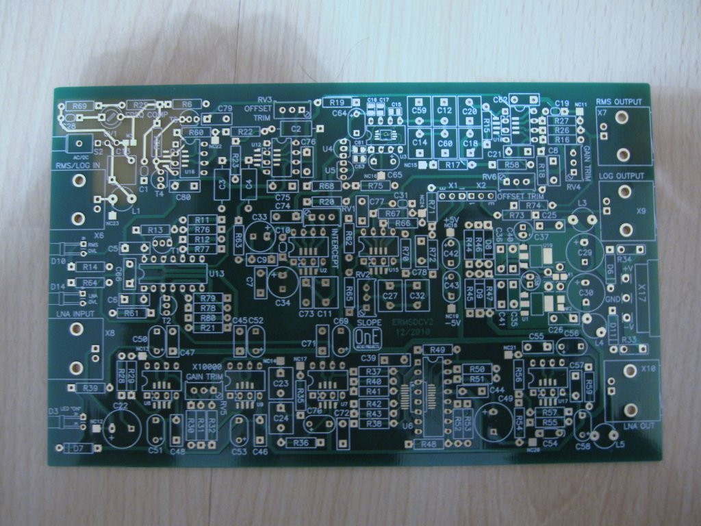
Very good job from pcbcart.
Normally, i will dispatch all of them before the end of this week.
🙂
Frex
--------------------------------
The 16 frebrury 2011
After the full test of my own PCB prototype, some little modifications are needed.
Many tests were performed with my prototype, i will post all results very soon in the dedicated thread.
I also prepare a complete new design folder with test and adjustments procedure, history file, and much more.
When it will be done, i will send it to all PCB buyers by e-mail.
Thank you !
Regards.
FRex.
--------------
The 20 February 2011
Hello,
I have do all measurements on my own PCB, the results are publisher on the dedicated thread HERE.
Good reading !
Frex.
-----
The March 12- 2011
Hello
I've doing many work on the project and i posted some new documents:
_ A user manual to understand and doing measurements.
_ A full measurements report do with my ERMSDCV2.
These documents can be downloaded below,
* ERMSDCV2_manual
* ERMSDCV2_report
Good reading !
Some PCB are available for sale, late buyers are welcomed !
Frex.
It's the group buy page for the design describe in this thread HERE.
It's a 100x160mm epoxy FR4 PCB, 2 layers, metallised holes, silkscreen, varnish mask, gold finish (RoHs).
All interested DIYers can add his pseudo and location in the list below.
The price would be 25€ for each PCB.
The price will include international shipping to EU,Canada and USA.
(Others country, please ask my by PM)
I will order professional PCB only if at least 10 PCB are ordered.
The buyers list start here :
|-
| class="tcat" | Name || class="tcat" | PCB Qty || class="tcat" | Location || class="tcat" | Paid || class="tcat" | Shipped || class="tcat" | Received
|-
| Frex || 1 || France || Yes || ---
|-
| Carpin || 2 || Netherlands || Yes || Yes || Yes 10 feb
|-
| MRupp || 1 || Germany || Yes || Yes || Yes
|-
| Andrew T.|| 1 || UK ||Yes || Yes
|-
| grenert || 1 || USA || Yes || Yes || Yes!
|-
| AR2 || 1 || USA ||Yes || Yes || Yes
|-
| ccliu || 1 || Taiwan || Yes || Yes || Yes (2/15)
|-
| musafir || 1 ||Italy ||Yes || Yes || yes
|-
| Valeriano || 1 ||Italy || Yes || Yes
|-
| Mother of PEARL || 2 || Canada || ||
|-
| fitzfish || 2 || USA ||Yes || Yes
|-
| schaikc || 1 || Netherlands|| Yes || Yes
|-
| matejS || 1 || Slovenia|| Yes || Yes || Yes
|-
| igwt || 1|| USA ||Yes || Yes ||Yes!
|-
| dfidler || 1|| UK || Yes || Yes || Yes
|-
| glao || 1|| USA ||Yes || Yes
|-
| gagnou || 1|| Grece || Yes || Yes || Yes
|-
Thank's
FREX
-------
The 01-februry 2011;
PCB are arrived today, it look like this :
Very good job from pcbcart.
Normally, i will dispatch all of them before the end of this week.
🙂
Frex
--------------------------------
The 16 frebrury 2011
After the full test of my own PCB prototype, some little modifications are needed.
The 2 capacitors of the low-pass filter formed by U12:A are inverted.
C2 must have 200pF value and C3+C4 value must have 100pF total value.
So, unsolder the capacitor C4(or C3), resolder it in parallel with C2 (100pF).
The two FET transistors (T4,T5) are mounted upside down.
For working properly, you can connect the pin 2 to pin 1 together, then you rotate it from 180° of the silkscreen legend.
R78 and R21 have wrong values, you must replace them
with 10kΩ instead of 100kΩ.
R55 is 49.9Ω (50Ω E96 value doesn't exist)
R15 and R56 are 909Ω (900Ω E96 value doesn't exist).
Many tests were performed with my prototype, i will post all results very soon in the dedicated thread.
I also prepare a complete new design folder with test and adjustments procedure, history file, and much more.
When it will be done, i will send it to all PCB buyers by e-mail.
Thank you !
Regards.
FRex.
--------------
The 20 February 2011
Hello,
I have do all measurements on my own PCB, the results are publisher on the dedicated thread HERE.
Good reading !
Frex.
-----
The March 12- 2011
Hello
I've doing many work on the project and i posted some new documents:
_ A user manual to understand and doing measurements.
_ A full measurements report do with my ERMSDCV2.
These documents can be downloaded below,
* ERMSDCV2_manual
* ERMSDCV2_report
Good reading !
Some PCB are available for sale, late buyers are welcomed !
Frex.
Attachments
Hello and happy new year to everybody.
At this time, 17 PCB has been pre-ordered.
I will close the pre-order list very soon.
In order to send the Paypal invoice to all buyers, please send me a private message (or e-mail if you have it) with your personal e-mail address.
Thank you.
Frex.
At this time, 17 PCB has been pre-ordered.
I will close the pre-order list very soon.
In order to send the Paypal invoice to all buyers, please send me a private message (or e-mail if you have it) with your personal e-mail address.
Thank you.
Frex.
Hello,
Normally, i will send a paypal invoice this week-end.
(I wait again e-mail of AR2 and fitzfish).
I add a little note about this design.
I have designed a prototype of this design using new ICs (LT1968) and the log converter (AD8307) has been added externally with my preferred "on the fly" design way..
When i've drawn the final schematic and the PCB, i've took great care to do it in "the art rules" to avoid any issues.
Nevertheless, i can not guarantee that the design will includes no error.
I prefer inform any DIYers in order to avoid any misunderstanding.
Regards.
Frex.
Hello,
All Paypal invoices were sent (except for Fizfish because no e-mail).
I will send the PCB order to PCBcart as soon all payments will be done.
The full design folder will sent by e-mail only at the end of the week to buyers.
Thank you.
Regards.
Frex.
All Paypal invoices were sent (except for Fizfish because no e-mail).
I will send the PCB order to PCBcart as soon all payments will be done.
The full design folder will sent by e-mail only at the end of the week to buyers.
Thank you.
Regards.
Frex.
The 01-februry 2011;
PCB are arrived today, it look like this :
Very good job from pcbcart.
Normally, i will dispatch all of them before the end of this week.
🙂
Frex
PCB are arrived today, it look like this :
Very good job from pcbcart.
Normally, i will dispatch all of them before the end of this week.
🙂
Frex
Hello,
Unless one, all letters were been sent right now.
Please, edit the wiki page when you receive yours to follow all shipments.
You can also just send me a little PM/e-mail. 😉
Thanks
Regards.
Frex
Unless one, all letters were been sent right now.
Please, edit the wiki page when you receive yours to follow all shipments.
You can also just send me a little PM/e-mail. 😉
Thanks
Regards.
Frex
Hi all.
I have just completed populating the two PCBs and drilling the face plates of the Hammond cases.
But I need help.
I tried powering the OSC board yesterday evening.
It draws ~70mA from both supply rails and the outputs of the regulators are sitting at ~9.9Vdc, the W test points show 0.32V and 0.33V across the 4r7 resistors.
The LT1230cn soic chip is too hot to hold my finger on it for longer than a couple of seconds. All others are cold to the touch.
Pin4 is sitting at +9.9Vdc and pin11 is sitting at -9.8Vdc.
There is only 2, or 3mV of Vdrop from the reg output @ W1 & 2 to the chip pins.
There is ~1.9Vac at the diff output X8 and at the X4 output. But zero at the X1 output.
The scope shows some distortion on the shape of the sinewave.
I have not tried any setting up yet.
Any ideas on what I should check, or measure, to identify my trouble?
Last edited:
- Status
- Not open for further replies.
- Home
- diyaudio.com Wiki
- PCB Group buy [1]- 1MHz RMS/DC & 90dB LOG converter with 80dB LNA