Hello kmj 🙂
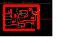
Looks good I think, you could move your 0.1uF on the V+ rail I guess. Put it between the Output L/R resistors and move your Output ground hole a little bit.
Looks good I think, you could move your 0.1uF on the V+ rail I guess. Put it between the Output L/R resistors and move your Output ground hole a little bit.
it might be a good idea to make and connect the input ground to the power ground by a thin track, otherwise distortion may get into the input signal.
Roushon
So just make the rail between the 0,1uF MKP cap and the inputground thinner then.
tobias_svensk
Just move the cap to the other side of the electrolyte then.
(those yellow things next to the out R and out L text are two VERY big capacitors )😀
I'll have to test your advice, i put it together this afternoon and it works. However, i get a loud background buzz, like a bad radioreception.
Will do.
The buzzing is still there and i stumbled on a strange problem.
It still works with the NE5532 op, buzz and all, but not with opa2604.
If i shut the pre down and change op the fuses melt. strange since the opa2604 only need about 5-6mA and the fuse is rated at 125mA-slow and the supply is a regulated 12V.
one shouldn't have any prblem with something as simple as this....
- Status
- Not open for further replies.
- Home
- Amplifiers
- Chip Amps
- PCB for simple OP-preamp