Member
Joined 2002
digi01 said:thank you Evilsizer🙂
If there is not shipping problems,I am glad to help you to buy some.its price is reasonable.
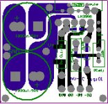
ok,the end pic.I am still need to find some quality wires to hook up all these patterns.
Looking good DIGI can't wait to try my boards soon.
Aunkst said:I soldered up 2 of my four today. I built these two on the cheap to use with the computer. they sound great. no hum. I am happy.
I will keep updating as I put them into some cases.
Hi Aunkst,congratulations!
I see the function of DC adj is shorted.what about the dc offset?
cheers
digi
I didn't have a trim pot on hand so I ignored it. eventually I will check the DC and insert a resistor if necessary. The last inverted LM3886 I built had on 10 mV of DC If this one measuers less than 30mV I will just keep it shorted.
As I said: On the cheap. I don't need Hi-Fi for the computer desk.
Nice board by the way.
Did you concider sending a trace from signal ground to the ground plane by the supply caps? For me I am going to try a short jumper and see if any ground loops come up.
As I said: On the cheap. I don't need Hi-Fi for the computer desk.
Nice board by the way.
Did you concider sending a trace from signal ground to the ground plane by the supply caps? For me I am going to try a short jumper and see if any ground loops come up.
Aunkst said:Did you concider sending a trace from signal ground to the ground plane by the supply caps? For me I am going to try a short jumper and see if any ground loops come up.
the signal ground and the power ground are separated specially in my edition.them should meet on the unique chassis ground(star G).
hey digi to make sure i get everthing hooked up correctly. the only thing im a little unsure of is how to connect the BLD board to the amp boards. Is it possible for you to make a drawing (BLD hooked up to two amp boards)?
thanks in advance
thanks in advance
Hi digi,
I just had a quick look at your connection diagram and was wondering if there might be a ground loop issue. I would normally connect ALL earths to the star earth.
I just had a quick look at your connection diagram and was wondering if there might be a ground loop issue. I would normally connect ALL earths to the star earth.
why not using T-network on inverted?
It's obvious that T-network used on feedback for inverted gainclone LM3886 sounds best (it's tested and compared), why you are not considering this way, please?
It's obvious that T-network used on feedback for inverted gainclone LM3886 sounds best (it's tested and compared), why you are not considering this way, please?
Re: Hummmmmmmm...
A nice little ground loop is created but it's hard to say if it will hum. digi, why don't you connect also the power grounds from the power supply to the ground star?carlosfm said:Connected that way, the amp will hummmmmmmmmmmm........😀
digi01 said:IMHO,What technology needs is real do, but not on the basis of the nitpick that is imagine.
Instead of taking my post as an advice, you take it as an attack.
Yes, the amp will hum if grounds are arranged that way.
This is practice, not theory.
You can choose to search the forum, as I talked about this too many times, or to ignore my post.
It's up to you.
Carlos, you were in good mood today. 
digi, if you will get hum or not this you will notice for sure sooner or later and if you really can see a groundloop the chance of getting hum is good. So the chances that Carlos is right is rather high.
digi, if you will get hum or not this you will notice for sure sooner or later and if you really can see a groundloop the chance of getting hum is good. So the chances that Carlos is right is rather high.
I don't say "the amp will HUMMMMM" but I can still see a loop in the ground. It may be nothing but a loop is clearly visible.
One of the reasons I strive to have only one pcb is mainly for the grounding problem. Many small pcb's has it's disadvantages when it comes to connect them.
One of the reasons I strive to have only one pcb is mainly for the grounding problem. Many small pcb's has it's disadvantages when it comes to connect them.
peranders said:Many small pcb's has it's disadvantages when it comes to connect them.
maybe,or not😉If these small patterns be assembled tight.
notice,in the 3886IGC board,the physical grounds of the power G and SG is separated.
Attachments
What I ment digi was all these wires involved which acts as antennas and creates ground loops. It reqiures more of the builder to get it right.
BTW,here is a good article from pass labs about ground.it is helpful.
http://www.passlabs.com/downloads/articles/ground-loops.pdf
http://www.passlabs.com/downloads/articles/ground-loops.pdf
peranders said:One of the reasons I strive to have only one pcb is mainly for the grounding problem.
You just need to know how to do it properly.
Digi: almost, but not yet.
Yeah, but one my reasons to have as much as possible on one pcb is to get less support questions. Almost every question about Gainclones are about wiring.
digi, the best thing you can do here is to connect your pcb's as you have drawn. Reality will get you the verdict.
Does it hum?
Completely silent => end of discussion.
digi, the best thing you can do here is to connect your pcb's as you have drawn. Reality will get you the verdict.
Does it hum?
Completely silent => end of discussion.
- Status
- Not open for further replies.
- Home
- Amplifiers
- Chip Amps
- PCB based invert 3886 chipamp assembly and comments