Hey guys.
I am working on the enclosure i plan for the Octal CCDA kit i ordered and i have a couple of question.

as you can see in the picture, the main PCB seats dead center and the power transformer seats to its left, with a metal barrier between them for shielding. the Pot and selector switch will be placed on the panel to the right of the PCB with shafts running to the front.
is this configuration "dangerous" given the distance between the transformer and PCB? am i just creating HUM problems for myself even with the barrier? would a Faraday cage on the transformer be enough to solve it or do i HAVE to move the PCB all the way to the other side of the enclosure?
thank you for your help
Tank out.
I am working on the enclosure i plan for the Octal CCDA kit i ordered and i have a couple of question.
as you can see in the picture, the main PCB seats dead center and the power transformer seats to its left, with a metal barrier between them for shielding. the Pot and selector switch will be placed on the panel to the right of the PCB with shafts running to the front.
is this configuration "dangerous" given the distance between the transformer and PCB? am i just creating HUM problems for myself even with the barrier? would a Faraday cage on the transformer be enough to solve it or do i HAVE to move the PCB all the way to the other side of the enclosure?
thank you for your help
Tank out.
Looks fine. I did the same thing for my preamp. I actually purchased a metal box from Digikey to shield the inputs and it holds a relay selector PC board. Belts and suspenders.
An externally hosted image should be here but it was not working when we last tested it.
air space and Iron
low carbon steel (cheap Iron) is an OK magnetic "conductor" ~ 100-1000x better than air- you can "short out" the leakage mag field lines that want to complete loops in air external to your transformer by making a box around the PS parts - perforated sheet lets air flow for heat management
a single flat sheet not much taller than the transformer won't be perfect - but closed 6 sided box also isn't absolutely necessary - U shape may be OK
and use air gaps too - mount the xfmr on non-magnetic standoffs if mechanically attached to the Iron shield sheet metal - may need mechanical damping if the xfmr leakage field makes the sheet vibrate = direct sound output
real paranoia/severe environments would use multiple Iron boxes - a 2nd around the amp board - but audiophiles worry about running signal near ferromagnetic material - lead dress, standoffs, and good pairing, twisting of wiring helps
hobbyist's often jump on Mu Metal - it is seldom competently applied - it saturates quite easily and should only be used where mag fields are already very low - cheap Iron is the 1st layer of defense - and usually all that is needed
very thick Al, Cu is needed to "reflect" 50/60 Hz mag field - wil cost lots more than Fe
Last edited:
A Faraday cage must completely enclose the emitter/receiver to be effective................... closed 6 sided box also isn't absolutely necessary - U shape may be OK
and use air gaps too - mount the xfmr on non-magnetic standoffs if mechanically attached to the Iron shield sheet metal
real paranoia/severe environments would use multiple Iron boxes - a 2nd around the amp board ..........
Does the same apply when considering magnetic fields?
my initial plan was to just throw a square piece of Fe in there, make sure it mechanicaly touches the upper pannel and floor (to close a circuit) and thats it.. but rust is a concern, so can i use stainless steel for that?
also, using U shape? how about this:
and what about the wood panel? should i cover it with metal to shield it as well?
also, using U shape? how about this:
An externally hosted image should be here but it was not working when we last tested it.
and what about the wood panel? should i cover it with metal to shield it as well?
physics notions of ideal or prefect aren't required, are never practically attainable
"effectiveness" has dimensions, thresholds in engineering - knocking a 60 dB SPL 50/60 Hz hum down by 20-30 dB will usually be enough in practice for home listening - even if the signal would still look poor by instrumentation standards
magnetic fields are all dipole (or higher) and fall off ~ 1/r^3 - so you can say mag fields really don't "like" traveling in air
this means you can get pretty effective "shadowing" with good mag field conductor and air spacing - just avoid the edges where the field is concentrated
the field lines from the open sides of the box will be really attenuated by the longer air path, much preferring to short through the mag conductive shield rather than loop around it
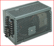
popper: are the top and bottom box covers Iron or Aluminum?
and leakage field will pass right through wood sides, thin non-ferrous metal - if your preamp is right against that side of your amp box then it could see the leakage
stainless may be poor or even completely non-magnetic - just use paint, plating if you are after some asthetic that prevents painting
"effectiveness" has dimensions, thresholds in engineering - knocking a 60 dB SPL 50/60 Hz hum down by 20-30 dB will usually be enough in practice for home listening - even if the signal would still look poor by instrumentation standards
magnetic fields are all dipole (or higher) and fall off ~ 1/r^3 - so you can say mag fields really don't "like" traveling in air
this means you can get pretty effective "shadowing" with good mag field conductor and air spacing - just avoid the edges where the field is concentrated
the field lines from the open sides of the box will be really attenuated by the longer air path, much preferring to short through the mag conductive shield rather than loop around it
popper: are the top and bottom box covers Iron or Aluminum?
and leakage field will pass right through wood sides, thin non-ferrous metal - if your preamp is right against that side of your amp box then it could see the leakage
stainless may be poor or even completely non-magnetic - just use paint, plating if you are after some asthetic that prevents painting
Last edited:
well, i was planning to make this from stainless steel (laser cut)..
it seems that covering the inside of the wood pannels with Fe will be a good idea also...
it seems that covering the inside of the wood pannels with Fe will be a good idea also...
probably wouldn't want to couple mag field to mag conductive cover sheet that stretches over your amp board too
better to have a complete sub box for ps
"old school" linear ps:
better to have a complete sub box for ps
"old school" linear ps:
Attachments
Last edited:
At least as important as shielding the transformer will be making sure the pairs of conductors to and from it are not good transmitting antennas, and that the input pairs are not good receiving antennas. To do that, keep each pair always close together, and tightly twisted. Input pairs could also be shielded twisted pairs, with shield connected to chassis ground at input end only.
Hi Tankpopper - PT orientation can also help. The magnetic lines of force exit/enter the transformer in-line with the laminations in an E-core transformer. The magnetic field is lowest off the ends of the laminations, and highest along the face of the windings.
Turing your PT so that the laminations "point" towards the rest of the amplifier, if you can. This will minimize the magnetic coupling. It is especially important to rotate the OPT so that the laminations are oriented 90 degrees to the PT laminations - again, to minimize magnetic coupling between the transformers.
Good luck! (and kudos on the chassis drawings - looks good!) 😎
- Status
- Not open for further replies.
- Home
- Amplifiers
- Tubes / Valves
- PCB and transformer placing and shielding