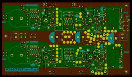
I am (trying) to build a PC88-ECC88 phono pre— I have gotten the bugger working and it measures and sounds fantastic….but…it is also oscillating and motorboating like crazy. Design is on a PCB and I used separate 100R CC grid stops for all 5 grids. Motorboating is obviously a PSU coupling issue but I cannot get the PC88s to stop squealing. I tried 470R CC grid stops with no luck so I must have a layout issue. Any tips on using high-gm tubes on PCBs?
There is ONE grid in PC88 with 5 connections. The intent is to widen the area as the tube is intended as a grounded grid element.
In your application i would remove all but one grid stopper and go from there.
In your application i would remove all but one grid stopper and go from there.
Correct - my description was wrong. However I did remove all but one grid stopper on the PCB with not much change. So, should I leave the unconnected pins floating and single grid stopper to one grid pin or connect all pins together and then fed from a single grid stopper?
I am no expert on these but a guess is that grid connections are already interconnected inside the tube, thus
no pins will be floating. In fact you might even be better off if you remove the copper to the non-used
pins thus reducing the area connected to the grid.
Use CC resistor to the plate to reduce inductivity and reduce Q . Some authors has descrived using ferrite
rings to further reduce Q
What frequencys is it oscillating with ? Or what is the symptoms ?
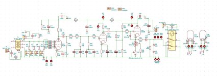
Supply is a zener follower. Bypasses are 100uF per stage 1Kohm inbetween each.
Oscillation is audible as a frantic thumping noise doesn't sound like 5/100Hz. However on scope all i can see is a sub 1Hz (0.8Hz as measured by my Fluke) and a small <5mV 100Hz wave with spikes. But the oscillation does not sound like hum nor is it that soft? Sub 1Hz would be PSU coupling so lower impedance PSU. Will update a sound file of the sound later
Oscillation is audible as a frantic thumping noise doesn't sound like 5/100Hz. However on scope all i can see is a sub 1Hz (0.8Hz as measured by my Fluke) and a small <5mV 100Hz wave with spikes. But the oscillation does not sound like hum nor is it that soft? Sub 1Hz would be PSU coupling so lower impedance PSU. Will update a sound file of the sound later
As I remember Morgan Jones recommended technique for high gm / mu tubes by connecting Wima fkp capacitor from anode to ground, value 0,1u or less ( can't remember exactly will look at balanced phono in third edition ) - this was I think anti-oscillatory measure.
From the look of the pcb grid resistors are right by the pins - but if they are on the pcb they could be less effective than connected from below directly to socket pins ( happened to me ones ).
Additionally Rod Coleman gave good advice for EC86 which has 3 grid pins - he used them all with higher value resistors since they are in parallel.
On the soviet version I used only one pin for grid, cut away other two from the socket.
So it seems this could be done in at least two ways - multiple grids : either one or all, which is best for PC88 I don't know but would like to find out since the tube interests me.
Last edited:
You could try a shunt zener regulator on the first stage replacing R7 with zener and adjusting R17 for correct current.
Mmm. Nice use of available pads. What I did do was increase the value of R17 to 4k7, and lo and behold, one channel stopped oscillating - well level of oscillation dropped severely, other channel remains the same - so PSU coupling was part of the issue. I now see that moving my hands (or body parts) near either input valve changes the volume of the oscillation - does this mean the valves are oscillating at a very high frequency and the capacitance of my body is affecting that "transmission"? Am going to try increasing the value of the now single grid stopper on each channel tomorrow....
Unfortunately I have removed the traces and grid stoppers from all but one pin.....but yes that was also my understanding with high gm tubes - that that one should use stoppers on all pins. I do have 100nF caps on all the anodes/anode resistors. I am using PCB sockets so short of Morgan's surface mount resistor trick the grid stoppers are as close as they can practically be. Next time I shall make the traces from grid stopper to grid pin much, much wider to minimise any inductance.As I remember Morgan Jones recommended technique for high gm / mu tubes by connecting Wima fkp capacitor from anode to ground, value 0,1u or less ( can't remember exactly will look at balanced phono in third edition ) - this was I think anti-oscillatory measure.
From the look of the pcb grid resistors are right by the pins - but if they are on the pcb they could be less effective than connected from below directly to socket pins ( happened to me ones ).
Additionally Rod Coleman gave good advice for EC86 which has 3 grid pins - he used them all with higher value resistors since they are in parallel.
On the soviet version I used only one pin for grid, cut away other two from the socket.
So it seems this could be done in at least two ways - multiple grids : either one or all, which is best for PC88 I don't know but would like to find out since the tube interests me.
As I said the the pre sounds quite good and at 500mV output distortion is below 0,03% (oscillation included) so PC88 may be a good option for phono stages but its not the most linear valve - see its characteristic curves. I am using it because i found 20 of them years ago - thinking they were some kind of ECC88 🤔
so figured I had to use the buggers....
You can try ferrite rings - reading Fred Musset blog he did that but with EC88 version - I'm wondering if PC version is more prone to oscillate but that is just my guessing in the dark.
PC version can be found dirt cheap so it interests me as possible alternative for soviet version of EC86 ( 6S3P-EV ). PC86 are also extremely cheap.
Hope you will resolve the issue with oscillation.
Regards, Krca
P.S. from what I remember looking at datasheet positive grid current starts at -0,5 on Vgk diagram / static conditions, with very narrow area for linear work - but I'm not an expert and this was just first look.
- Home
- Amplifiers
- Tubes / Valves
- PC88 layout tips?