I purchased this SMPS>>http://www.intextechnologies.com/dproduct.asp?cat=Peripherals&sub=SMPS
400w rating.The specs on the website show 10A for 12V but on the sticker on the SMPS its written 12V at 20A.Whatever...
Its more than enough for a single supply chipamp.
Do I need to keep the +5V busy too(with some load) so that the SMPS runs fine.
Since the curent capability is high,i dont think there is a need to modify the internals for more current.I plan to hook it up directly to the amp to provide +12V dc....for that is it essential to load the +5V too?do i need to load rest all the outputs too?if yes...how to do it?
Moreover,its an ATX PSU with something as PWR ON pin, so if i use it outside the pc,which two or three etc etc wires need to be connected(shorted) in the 20pin connector so that the SMPS can operate outside the cabinet(does the green one mates with black one?)
Sagar
Sagar,
You should load down the +5V line for about an amp or two to get the full 12V out. An even better approach to this would be to modify the supply by rewinding the transformer's secondaries to give out a true +13.8V, and eliminating the +5V line all together.
Not too difficult to do, of you have some experience, and there are several threads here in the Forum on that subject. Just my $0.02 worth.
Steve
Each reply is worth a million(to say the least).
I sifted thru all the threads on this forum to mint out the required info but to no avail.
For loading +5V, couple of LEDs lying waste in my component box seem to me as suitable candidates OR is there a better approach?
SMPS gives +13.7V dc at no load🙂[switched on by shorting pins 11 and 12]
Can suitable modifications be carried out easily to enable the SMPS to supply bipolar outputs for dual supply amplifiers?
Sagar
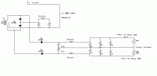
but thats only + -12V.
the amp will only purr at such low volts.
The resistance needs a heatsink?
Sagar
the amp will only purr at such low volts.
The resistance needs a heatsink?
Sagar

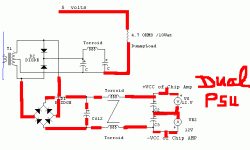
Can you please tell the component values and how come voltage gets to +- 25V?
What is this T1 etc etc,are they in the SMPS or these are the modifications to be done?
Torroids are to be rewound?
If u have tried this out, can u post the pics too?
Sagar
What is this T1 etc etc,are they in the SMPS or these are the modifications to be done?
Torroids are to be rewound?
If u have tried this out, can u post the pics too?
Sagar
Sagar-
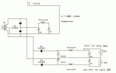
+/-12V is already available from the SMPS, however the -12V is only about an amp, or so. To get the full -12V current,
you will need to swap out the two small 1amp diodes on the -12V line for a couple of heavier-duty ultrafast or schottky diodes, rated at, say 8A, 200V. Or, you could go with a common-anode double diode, like those found in most car amps. This would enable you to use the full -12V and get you the +/- bipolar supply you need.
BTW, the last schematic shown will only generate +/-12V, not +/-24-25V, because it's center-tap reference is still halfway across the secondary.
PS, love the Avatar! 😀
Steve
Names Sagar.....please edit that🙂
wont the replacement of diodes saturate the core too soon or will it be able to tolerate the inreased output?
rewinding the +5V will require fiddling with the overvolatge error amp in the supply,Am I right?
love Kylie
Red Blooded woman.
Sagar
Names Sagar.....please edit that🙂
wont the replacement of diodes saturate the core too soon or will it be able to tolerate the inreased output?
rewinding the +5V will require fiddling with the overvolatge error amp in the supply,Am I right?
love Kylie
Red Blooded woman.
Sagar
Yes, anything involved in the voltage feedback and over-voltage sensinf will need to be re-done to work with 12-13.8V (or whatever voltage you end up choosing). The TL494 PWM controller chip ( I assume that is the chip in your supply) does not use the +5V to run, it runs off an auxiliary diode tapping the 12V winding, so getting rid of the 5V windings will not affect operation of the PWM chip.
Disassembling the main transformer is, by far, the trickiest part, but it will solve alot of your problrems. To start, you should either bake the xfmr at 350F-400F for about 30-45min. This should cause the lacquer finish to release the core halves. Let the xfmr cool, and begin the disassembly process by removing the windings one at a time, counting the number of turns for each.
You may notice the half of the primary is wound outside the secondaries, and the other half is wound inside the secondaries. This 'surrounding' of the secondaries by the primary ensures good coupling between the primary and secondaries.
Now that the main xfmr is ready to be reinserted on the main board, find the components that sense the +5V section and re-adjust their value(s) as previously mentioned. As for the -12V section, try the common-anode double-diode. If there's not enough space on the pc board for this, you will need to rig something up. I have used the space for the old +5V rectifier for the new +12V section, and the space for the old +12V rectifier for thew new -12V section. Some modding of the pc board traces may be necessary, especially to connect a filter cap between the BIG yellow/white toroid and the filter inductor for the old +12V section, since many pc supplies lacked a filter cap between these two coils.
You will also want to rewing the BIG toroid with a new bi-filar winding to provide good cross-regulation between the two outputs, much like before.
Using the number of windings on the +/-12V windings as a reference, increase the number of turns from original by about 2 turns. Of course, you will need new wire, but it is well worth it.
Since you will be eliminating the 5V section, this will give you more than enough area on the bobbin to fit a higher-current 12V winding.
When you're finished (remember to first wind half the primary, the secondaries, then the other half of the primary to ensure the aforementioned good coupling), use some transformer tape, and perhaps some of the same sticky gooey stuff that originally held the two core halves together.
Wow, I just realized that I've been woirking on this reply for about 45min, so I will stop here and catch my breath.
Steve
Steve:
Do you get QEX ? -- the July issue has a boffo SMPS for a tube KW linear -- this thing will really light up the lights.
Jack
Do you get QEX ? -- the July issue has a boffo SMPS for a tube KW linear -- this thing will really light up the lights.
Jack
QEX'ing
Jack-
No, I get QST. Do you have a link for the QEX article? July QEX is not on the ARRL's website yet. Who is the author? Callsign?
WOW! Just lookin' at my last post. Did I ever have alot of typos in it, or what?!? I must be getting tired, and it's only 3pm! ARGH!
Sagar- the other method I have for disassembling the xfmr core is to submerge the whole assembly in either Acetone, Paint Thinner or Lacquer Thinner. I have found that Acetone works the best.
Steve
Its very difficult to trace the circuit of modern AtX supplies and modify it for the simple reasons.....
1)Most resistors are 1/8 watt.
2)All output voltages +5V;-5V;12V;-12Volts;3.3V are sensed for over/under voltages.
3)Presence of 5v/1amp standby supply.
It would be easier to modify old PC AT PSU's.Get an old one (I have got a half a dozen of em free from a service shop)Replace old electrolytic capacitors....etc
Hi,
I have similar soolution with N-Channel, but I replace all secondary winding with very thin wire and let the original circuit exist if you don't know anything. Then add new winding as normal as half bridge but with ultrafast diode. The new winding have no connection at all with ATX PSU circuit.
The advantage replace totaly secondary winding and use thin wire is very easy to connect pin to pin. While the new winding is not need to connected to transformer pins but you may connect directly with add extra small board that contain diodes, elcos, and filters.
I run my amps more than one year with no problem.
See the link as my suggestion to Carlos. I don't know what papa's progress until now.
http://www.diyaudio.com/forums/showthread.php?s=&threadid=74310&perpage=10&pagenumber=6
But remember: WARNING! You deal with fatal risk, high voltage that may cause injury or death.
AT -v- ATX
Yes, An AT psu is what I was referring to. You could use an ATX, but it would be much more difficult, and you would have to eliminate the +5Vsb section anyway.
Since old AT spuulies are plentiful and cheap, this is your best bet. Start out by getting a bunch of different models because they all has slight variations on their internal circuitry and component layouts. Pick the one that will best lend itself to the mods.
- Status
- Not open for further replies.
- Home
- Amplifiers
- Power Supplies
- PC SMPS querries