Hi All,
Maybe someone can give me some advice for positioning the PC boards in my amp.
I am building a Leach amp in an exisisting amplifier housing, and I have 2 easy locations to put the amp boards. I am using 8 individual heat sinks for the 8 BJT's, clamped together into 2 roughly cubical heat sink assemblies. I can easily put the PC boards above these assemblies, or over on one side of the case. Any other option will be quite difficult.
If I put them above (about 1/2", or 1.2cm above the heat sinks with the components on the upper side), I will restrict the airflow, but not entirely. The leads to the BJT's will be short and uniform.
If I put them to the side, the heat sinks will get good airflow, but the leads to one channel will be about 10" (25cm) long. I worry about stability.
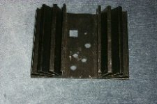
The heatsink assemblies are about 4x4x3" (10x10x7.5cm), and densely finned.
Any opinions, advice, etc.?
Thanks, Dan.
Maybe someone can give me some advice for positioning the PC boards in my amp.
I am building a Leach amp in an exisisting amplifier housing, and I have 2 easy locations to put the amp boards. I am using 8 individual heat sinks for the 8 BJT's, clamped together into 2 roughly cubical heat sink assemblies. I can easily put the PC boards above these assemblies, or over on one side of the case. Any other option will be quite difficult.
If I put them above (about 1/2", or 1.2cm above the heat sinks with the components on the upper side), I will restrict the airflow, but not entirely. The leads to the BJT's will be short and uniform.
If I put them to the side, the heat sinks will get good airflow, but the leads to one channel will be about 10" (25cm) long. I worry about stability.
The heatsink assemblies are about 4x4x3" (10x10x7.5cm), and densely finned.
Any opinions, advice, etc.?
Thanks, Dan.
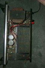
Layout of Amp case
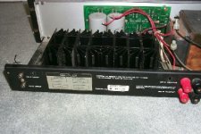
Here you can see the layout of the amp case. I'll clean it up and repaint the transformer so it is not so embarrasing, but I wanted to leave the components where they were. Besides the transformer, you can see the power supply board and the LED driver board.
Here you can see the layout of the amp case. I'll clean it up and repaint the transformer so it is not so embarrasing, but I wanted to leave the components where they were. Besides the transformer, you can see the power supply board and the LED driver board.
Attachments
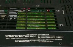
another view
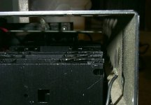
Here is another view of the PC board above the heatsinks. The other option for mounting the boards is vertically in the large space to the left of the heatsinks. Notice the long wire runs that would be necessary to connect the output devices to the boards. The big question is - would the boards get too hot, or the heatsinks not get enough air if I mount the boards on top like this (with a 1/2" or 1.2cm air gap between the board and the heatsinks).
Thanks again for any advice!
Attachments
i think those finned sinks are designed to be side mounted, but have you thought about running, say, 1 or 2 12v pc case fans and ducting the airflow to the fins to isolate them so you can avoid any noise they may introduce. you could situate the fans over in that space on the left? i think the term is "forced convection" or something. from your pictures an idea i got was also the possiblity of mounting fans on those vents, blowing down into the fins, but the i guess the pcb gets in the way. i believe it's pretty easy to thermostat control them too so they kick in when they're needed.
i've always though that enclosure architecture is by far the most difficult and frustrating part of building a diy amp! i recently spend weeks trying to avoid long rail power supply lines and i eventually just put the power transformer, etc in a separate shielded box that now has to sit on or under the main box. looks ugly but it works!
i've always though that enclosure architecture is by far the most difficult and frustrating part of building a diy amp! i recently spend weeks trying to avoid long rail power supply lines and i eventually just put the power transformer, etc in a separate shielded box that now has to sit on or under the main box. looks ugly but it works!
There is a problem with this configuration that no one has addressed yet: Where are you going to thermally track this amplifier. With separate heat sinks, thermal run away is immenent. Also, the boards should not be mounted over the heatsinks. They need to vent. It won't damage the board, but everything will run extremely hot and due to inaccurate thermal tracking due to individual heatsinks, you will have thermal runaway and maybe second breakdown in the transistors. You can use two heatsinks per channel (one for the two PNP and one for the two NPN) but not one per transistor. But these two things are easy to fix. Good Luck!!!
BeanZ
BeanZ
Peter, Between the PSU caps and the heatsinks is where I want to put it, but there is just not enough room without rebuilding the power supply. Since everyone is so negative about the boards above (As I figured, but there is always hope), maybe I will just have to re-configue the whole thing. Maybe if I move the caps I can flip up the PSU board vertically as well.
BeanZ, the Leach Amp uses 4 discrete diodes for thermal tracking. I was planning to mount one diode per heatsink, and also bonding the 4 sinks on each channel together with throughbolts and thermal paste. What do you think of that arrangement?
newmz, no fans! I would like to keep this unit fan-free if I can. I think I have enough HS area for that if I can get good airflow through the vents.
Thank for the responses!
Dan
Using one diode per heat sink in not a very good idea. The PNP and NPN transistors will run at different temperatures. Thermal runaway is likely to occur. Buy some bigger heatsinks. Get some that hold 4 TO-3 packages.
BeanZ
BeanZ
Hmm, I thought I had a brilliant idea going there, but I went back and reviewed my notes, and I found where my idea is specifically proscribed. I read where the bias diodes need to see the average of the transistor temperatures, and somehow I got the idea in my head that one diode per transistor would average out... It doesn't work that way though.
At the risk of sounding obstinate, I have a bunch of these heatsinks and would really like to use them up. I read that a successful Leach amp can be had by splitting the NPN and PNP devices on 2 heat sinks, and using 2 diodes per heatsink.
What if I soldered 2 heatsinks back to back, and attached the 2 NPN to this assembly, then did the same thing for the 2 PNP (per channel)?
Thanks again, Dan
- Status
- Not open for further replies.
- Home
- Amplifiers
- Solid State
- PC board position