I bought a pair of these, thought they were too good value to not try...
Dayton Audio PC105-4 4" Full-Range Poly Cone Driver
I've been trying to model a parallel notch for the 8.5Khz peak in Xsim using Dayton FRD & ZMA files, but not really getting anywhere, I'm fairly new to Xsim, so any suggestions for component values or other hints welcome.
I'm getting the idea that it's probably not a good idea to model the notch by itself, even though it would be nice to do only that; I probably need the other xover components as well (Likely to cross it over to tweeter at ~ 4Khz)
Edit:
Hmmm, just opened my last weekend's attempt, seems like a series notch is much easier.....
Last edited:
Using a tweeter? And yes- an LC across it as much better with the voltage divider out front.
Later,
Wolf
Later,
Wolf
I can’t help you much with Xsim sorry Pete, but I sometimes find it a little easier getting rough values for the notch filter by trial and error (works if you have a number of crossover bits floating around), using the Dayton impedance tester rather than the measurement mic. I’d do a rough XO, then work on the series notch - Just look for the increase in impedance at the point in question on the graph. After this I set up the mic and start fine tuning the whole crossover including the notch R/L/C values.
That method of empirical data creation works for parallel notches, but not for series notches. The Le of the lowpass has to be present, and it swamps the LC characteristics. Without the coil present, the filter won't work as it needs the voltage divider.
Later,
Wolf
Later,
Wolf
(Likely to cross it over to tweeter at ~ 4Khz)
I wouldn't worry about the peak if you're crossing at 4kHz to a tweeter.
Especially when it's 2nd order or more.
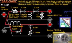
Thanks for all the input guys, esp. Wolf Teeth for the schematic.
Re:'I wouldn't worry about the peak' - that's my usual approach, but I want the best out of this driver... Possibly using it to convert a 2 way (SEAS CA18RLY + 22TFF) to a 3 way. (Also bought TG9s, it'll be interesting to compare)
Actually, a bigger problem for me is FRD/ZMA files for the SEAS drivers, I've tried FPGraphTracer which is supposed to be really easy, but I can't get results I'm happy with.
Often the LP filter takes care of the peak for you, making a notch unnecessary.
But yeah, do everything else first, then see where you are at.
But yeah, do everything else first, then see where you are at.
The peak only appears on the 0° and close angle measurements. If you don't want to filter the driver and it does not show a resonance ridge at the waterfall decay measurement, I would not use a notch filter and instead use a acoustical-mechanical filter. Run two wires in an x-shape over the driver and put a ~2-2,5cm diameter piece of felt above the dustcap on the wires. That will most likely kill the peak on axis and low angles but still keeps the sonic energy bilance in the room much more even than an electrical filter would, at a cost next to nothing. Measure the decay and the angled response first to decide what's the better option.
E: You'll probably have to filter the baffle step anyway, so a completely different solution would probably better.
E: You'll probably have to filter the baffle step anyway, so a completely different solution would probably better.
Last edited:
- Status
- Not open for further replies.
- Home
- Loudspeakers
- Multi-Way
- PC-105 peak notch