Member
Joined 2009
Paid Member
OH!!!
HEAT! From the Cap Multiplier!!
I really forgot about its existence after connecting it for the second time. With 2.2A, it was not much hot. But from today morning it's carrying 3A and has become the hottest part in the system! Well, not unmanageably hot though; can place my fingers on its heatsink for about five seconds.
Running the follower in 3Amp quiescent current. 24V supply. Clearly a better sounding config. Summertime failsafe test, in spring 🙂, Whatever. Everything's going as well as expected except the multiplier. I need a fan.
Another news,
I have been reporting Rod Elliot about my modifications on the CCS since the day PMA suggested me to do so in December and the original article in the audio pages has been updated with the FET CCS mods on the follower. Rod is a kind guy.
Project 83 - MOSFET Power Follower
.....
Last edited:
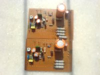
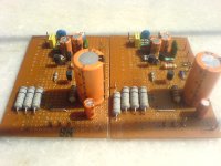
The Boards.
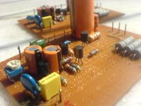
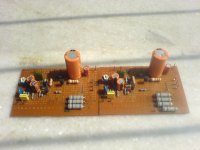
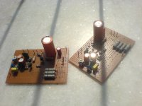
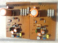
Here are some pictures of my version of DoZ+MPFv2. Both on dot boards, and are the final ones for the system.
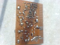
The extra 1ohm/2watt resistor seen in one of the boards is the one configured for the summertime 24V/3Amp setting. The other board is going through the same process now. The underside has become "scratchy" in a part of the layout, this happened while removing the BIG 1ohm/10watt resistors. Otherwise I am happy with these.
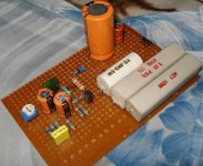
The "work on progress" version of the original MPFv1 on the same boards can be seen in the last attachment. It was taken around September or so. Note the 2.2+4.7ohm resistors to form a 1.5ohm resistor 😱.
Cheers.
Here are some pictures of my version of DoZ+MPFv2. Both on dot boards, and are the final ones for the system.
The extra 1ohm/2watt resistor seen in one of the boards is the one configured for the summertime 24V/3Amp setting. The other board is going through the same process now. The underside has become "scratchy" in a part of the layout, this happened while removing the BIG 1ohm/10watt resistors. Otherwise I am happy with these.
The "work on progress" version of the original MPFv1 on the same boards can be seen in the last attachment. It was taken around September or so. Note the 2.2+4.7ohm resistors to form a 1.5ohm resistor 😱.
Cheers.
Attachments
-
 DSC01229.JPG222.6 KB · Views: 539
 -
 DSC01227.JPG206.1 KB · Views: 514
 -
 DSC01226.JPG224.7 KB · Views: 507
 -
 DSC01228.JPG224.1 KB · Views: 496
 -
 DSC01231.JPG287.8 KB · Views: 497
 -
 DSC01230.JPG217.2 KB · Views: 178
 -
 DSC01232.JPG229 KB · Views: 162
 -
 DSC01234.JPG233.9 KB · Views: 199
 -
 DSC01590.jpg82.3 KB · Views: 213
Member
Joined 2009
Paid Member
It's looking good Shaan !
On the topic of output emitter resistors. I added these to my simulations. They certainly do a good job of controlling the temperature sensitivity of the bias current. They don't do it any better than putting a temperature compensation diode on the heatsink. But I have realized that I was assuming perfect 'negative thermal feedback' for the diode approach. What I failed to recognize was the fact that the temperature of the silicon in the power device package can heat up pretty darn fast and it takes some time for that temperature rise to 'charge up' the thermal capacity of the heatsink. My diode temperature sensor would never be able to react fast enough to save the power device. On this basis, it's all starting to make sense again.
Perhaps those ThermalTrak diodes in-package can be used to avoid the need for those emitter resistors ?
Member
Joined 2009
Paid Member
Then we must wait for Silicon Carbide and/or Diamond devices. And there are signs that they will come.
Why should we wait, if we can implement a feed-forward approach, like I did in my Tower amps? No reactive feedback; proactive correction of errors before they appear.
All roads lead to Rome... But not everyone see them yet. 😉
All roads lead to Rome... But not everyone see them yet. 😉
Shaan,
congratulations to your contribution to Rod Elliott's webpage.
Regards,
Thanks. How do my boards look? 😀
Treat from me on my bday and on the finalization of the follower boards.
YouTube - Ayaka's Surprise English Lesson: Abe Natsumi (2001-07-03)
and
YouTube - Ayaka's Surprise English Lesson: Yoshi Hitomi (2001-08-03)
and
YouTube - Ayaka's Surprise English Lesson: Tsuji Nozomi (2002-09-11)
In the vids someone is trying her best to help some of the greatest pop idols of Japan speak English. Some of my favorite youtube people whom I pass my free time with. Enjoy.
Only thing about this is the electrolytics on the output. Is there any way to use a smaller cap with a tranformer coupling on the output?
Won't it transformer degrade the sound? I think buying a great Elna(or any great make) cap at half the price of the transformer would be better...
cheers/
cheers/
Both caps and transformers do degrade the sound. A great transformer will sound better than a crappy cap and vice versa.
A great Cap always costs less than a great Transformer.
A shame that we can't eliminate both in an se class-a amp like this. But wait, this is the way life works. Either Cap or Tranny. Choose your poison, expensive poisons taste sweeter. 😀
A shame that we can't eliminate both in an se class-a amp like this. But wait, this is the way life works. Either Cap or Tranny. Choose your poison, expensive poisons taste sweeter. 😀
Last edited:
A good electrolytic cap paralleled with a big film cap will make forget about an output TX.
Petp Capacitors-one Of The Best? - diyAudio
...safe if dear Wavebourn invents one of his strange ideas with trifillar output Tx (about which I never dare to ask...) 😀
Petp Capacitors-one Of The Best? - diyAudio
...safe if dear Wavebourn invents one of his strange ideas with trifillar output Tx (about which I never dare to ask...) 😀
A good electrolytic cap paralleled with a big film cap will make forget about an output TX.
That's it. The next best o/p config after direct-coupled.
I have heard transformers that didnt sound at all (and that were sufficiently extended in bandwith too). The only problem is cost, several times more than a good pair of caps.
Big caps are recomended, moreover if they are not included in a feedback
loop to correct the low frequency losses..
My "24/7 always on" amp is capacity coupled, and i use 2X10000uF for
each channel...
loop to correct the low frequency losses..
My "24/7 always on" amp is capacity coupled, and i use 2X10000uF for
each channel...
The only problem is cost, several times more than a good pair of caps.
eletrolytics? Certainly not 1000uf film caps.
My "24/7 always on" amp is capacity coupled, and i use 2X10000uF for
each channel...
😱
😎
- Status
- Not open for further replies.
- Home
- Amplifiers
- Solid State
- Pavel's MOSFET Follower - No Darlington Mod