Hi guys,
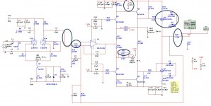
Just found a schem of Pathos C1 MK3, a hybrid mosfet amp.
The simulations are good, 0.6Vrms 1KHz, THD 0.022%
However, some values on the schem are not readable, and here's what I am confused.
1. the +-V supply value? (According to it's PS, should be more than 30V)
2. the output inductance value?
3. R35
4. R11
Also, when I load a 8ohm, things get bad(ugly waves), I have to disconnect D4/D5 to prevent error.
Please comment, I really love this design
Attachments

Last edited:
With 50V rated caps, it would have to be about +/- 35 V to +/- 45 V.
20 turns, 10 mm dia. with decently fat wire - you can use an online cylindrical inductor calculator, but expect 1-2 mH.
The original counterpart to R11 (R112) pretty clearly says 5K, so a 4k7 or 5k1 it is. Certainly not a value optimized for a little low-noise hottie like the AD797, try finding something a little more adequate.
First I think you should correct R32, where you used 50k rather than 4k7.
R35 seems like a bodge resistor put in during production, you could clearly accomodate that using R34 only. Connect amplifier output and input to ground and vary R34 until currents through R25 and R26 become equal at pot midpoint.
It's a pretty clever circuit in that it gets away with a bunch of 45V rated transistors on much higher supplies by having voltage gain in the output stage. In return, I presume you'll have to run these FETs a bit hot...
With 50V rated caps, it would have to be about +/- 35 V to +/- 45 V.
20 turns, 10 mm dia. with decently fat wire - you can use an online cylindrical inductor calculator, but expect 1-2 mH.
The original counterpart to R11 (R112) pretty clearly says 5K, so a 4k7 or 5k1 it is. Certainly not a value optimized for a little low-noise hottie like the AD797, try finding something a little more adequate.
First I think you should correct R32, where you used 50k rather than 4k7.
R35 seems like a bodge resistor put in during production, you could clearly accomodate that using R34 only. Connect amplifier output and input to ground and vary R34 until currents through R25 and R26 become equal at pot midpoint.
It's a pretty clever circuit in that it gets away with a bunch of 45V rated transistors on much higher supplies by having voltage gain in the output stage. In return, I presume you'll have to run these FETs a bit hot...
Thanks for reply🙂
I have 2 more questions:
1. the original design uses a Volume IC between tube/trans, can I just connect them with some resistor?
2. Is this a reliable design that I could connect 2 Zeners near MOSFET? (even something went wrong with simulation?)

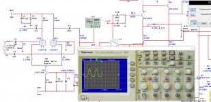
Seems your amp is happily sourcing current but hardly sinking any. Is the opamp hooked up correctly? How does the signal look after R29?
You can bypass the entire tube preamp section and attach the signal source after R29 for the time being.
Oh, and above I wrote mH but meant µH. A cylindrical coil 1 cm in diameter and 2 cm long gives about 1.6 µH.
You can bypass the entire tube preamp section and attach the signal source after R29 for the time being.
Oh, and above I wrote mH but meant µH. A cylindrical coil 1 cm in diameter and 2 cm long gives about 1.6 µH.
- Status
- Not open for further replies.