I've been reading through patent #5710522 trying to understand the basics behind Nelson's active current source setup. I bumped into this topic after having read this thread where kenpeter at post #12 says :
In column #2 line #35~40 of patent #5710522 Nelson describes the behaviour of the current feedback loop and I can't help but think this is quite similar to the behaviour of the split sense resistor setup from kenpeters post. While building my Zen from recycled computer supply components I've modified my currentsource to include the split resistor setup:
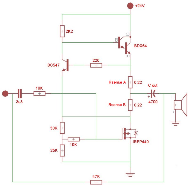
When the input signal swings negative, IRFP440 becomes less conductive causing the current through Rsense B to drop and Rsense A to rise because Cout is being charged through the attached load. Whereas with a single Rsense the max loading current would be about 1.4A (0.66/0.47), this time the maximum loading current is 3A (0.66/0.22). As soon as the Cout is filled the idle current gets distributed evenly over Rsense A and Rsense B again resulting in a idle of 1.4A
The same applies for the positive signal swing where the IRFP440 becomes more conductive causing the current through Rsense B to rise while unloading the charge from Cout through IRFP440. The rise in current over Rsense B will cause BDX64 to become less conductive further lowering the current through Rsense A.
Looking at the original patent I can't help but wonder if the split sense resistor setup accomplished the same without R5 and C1 ?

Now the big Q is if this all sounds better and, listening to this setup while I type, I must say it does ! Somehow Zen seems to be in better control of the woofer.
kenpeter said:And if you connect the load halfway into the sense resistor??? Does this make an active current source of equal impedance? Hate to throw away double free power... If you are making it anyway...
In column #2 line #35~40 of patent #5710522 Nelson describes the behaviour of the current feedback loop and I can't help but think this is quite similar to the behaviour of the split sense resistor setup from kenpeters post. While building my Zen from recycled computer supply components I've modified my currentsource to include the split resistor setup:
When the input signal swings negative, IRFP440 becomes less conductive causing the current through Rsense B to drop and Rsense A to rise because Cout is being charged through the attached load. Whereas with a single Rsense the max loading current would be about 1.4A (0.66/0.47), this time the maximum loading current is 3A (0.66/0.22). As soon as the Cout is filled the idle current gets distributed evenly over Rsense A and Rsense B again resulting in a idle of 1.4A
The same applies for the positive signal swing where the IRFP440 becomes more conductive causing the current through Rsense B to rise while unloading the charge from Cout through IRFP440. The rise in current over Rsense B will cause BDX64 to become less conductive further lowering the current through Rsense A.
Looking at the original patent I can't help but wonder if the split sense resistor setup accomplished the same without R5 and C1 ?
Now the big Q is if this all sounds better and, listening to this setup while I type, I must say it does ! Somehow Zen seems to be in better control of the woofer.
Last edited:
The advantage of the Aleph circuit is that the values of
DC and AC are easily adjusted independently.
😎
DC and AC are easily adjusted independently.
😎
Those two split resistors are employed to force the transistor on top to double the output current from the bottom tr. into the load. (for efficiency,
which is not impressive, when that top tr. serves as a CCS).
Simple math:
Ra*It+Rb*Ib=constant (which is Ube of the bipolar tr. in the FB loop)
Since Ra=Rb, then It+Ib=const. Now, switching to deltas,
dIt=-dIb, and dIout=2dIb, which is the result of Push-Pull action of the SRPP principle, employed in your, and similar circuits.
So, again, the circuit employs the feedback loop to force the top transistor to
produce the desired effect.
- Status
- Not open for further replies.