MJL 21193
I have just finish front end power to both channels for my Goldmund clone with the changes you recommended in # 105, and it worked perfect.
I am looking forward to listen to the Goldmund with this latest changes later to night.
Your power unit, I think, will function way beyon the original voltage dopler.
Your measurements confirm my assumptions.
Eivind Stillingen
To be honest almost any decent design would outperform what they came forth with
Nico
Nicco Ras
Very interesting power you brought i #118. You said something about what current this unit could deliver. Can you give other data, what voltage in/out.
You also said you have a PCB for this unit. I am very interested.
Eivind Stillingen
Very interesting power you brought i #118. You said something about what current this unit could deliver. Can you give other data, what voltage in/out.
You also said you have a PCB for this unit. I am very interested.
Eivind Stillingen
Eivind, I don't want to hijack John's thread so if you would like e-mail me nico_ras@digisec.co.za and I will give you any information you need. BTW I meant I have PCB Gerber files not PCBs.
No problem Nico, it's (nearly) a dead thread anyway since I'll be starting up another dealing specifically with the new build.
I didn't get the chance to etch that main supply board yesterday - today for sure.
Edit: Actually, I will be reopening this thread eventually. I will continue with the upgrade after the new amp is built.
I didn't get the chance to etch that main supply board yesterday - today for sure.
Edit: Actually, I will be reopening this thread eventually. I will continue with the upgrade after the new amp is built.
Last edited:
Built and tested the main supply board:
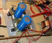
nothing too taxing yet since I'm a bit nervous about my isolation washers on the power transistors. Yes, they are paper - I'll need to dig deeper in my mess to find some mica.
Running off of a 40-0-40 transformer, I adjusted the output down to +/-50VDC and it looks good, free of ripple. I did a low power transient test (switching between 330 ohms and 165 ohms on the output, which translates to ~150mA and 300mA) and it looks clean, fast and stable. I'll do a higher power test later, switching between a 1A and 2A load.
Paving the way for the new build, I ordered 4 heatsinks from barrredboss on Ebay. 8.5" wide x 8" tall. 2 per side will give me the same depth as the ones on my original 6 channel (those I actually made myself. I'm not going through that again - too much work) but 2" taller. The new build will have the same 'look' but will be taller.
Built and tested the main supply board:
nothing too taxing yet since I'm a bit nervous about my isolation washers on the power transistors. Yes, they are paper - I'll need to dig deeper in my mess to find some mica. . . .
Wow! Where can one purchase mica?
I bought mine from Digikey - they are TO-3 and I trimmed them down to fit the TO-264 package. Used a standard hole punch to punch a new hole for the mounting screw.
Moving forward, I don't have the right power resistors to make suitable dummy loads for the 1A, 2A transient response. I did have enough for a ~500mA, 1A transient response test:
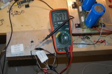
~110 ohm (3 x 330 ohm in parallel) paralleled with 110. Switch is a MTD3055V mosfet driven by a 5V, 1k squarewave from my function generator.
How it looks:
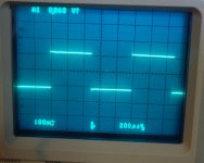
scope probe is at 1x, so there is roughly 200mVpp on the switch from 500mA to 1A.
Close up of the leading edge at 15x magnification:
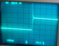
touch of ringing? Not sure if this is a problem. Suggestions?
Moving forward, I don't have the right power resistors to make suitable dummy loads for the 1A, 2A transient response. I did have enough for a ~500mA, 1A transient response test:

~110 ohm (3 x 330 ohm in parallel) paralleled with 110. Switch is a MTD3055V mosfet driven by a 5V, 1k squarewave from my function generator.
How it looks:

scope probe is at 1x, so there is roughly 200mVpp on the switch from 500mA to 1A.
Close up of the leading edge at 15x magnification:

touch of ringing? Not sure if this is a problem. Suggestions?
I don't know. I don't know if it's a problem either.
I guess the best way to test this supply is to power what it is supposed to supply - an amp. I'll hook it up to an Abomination module and see how it does.
I guess the best way to test this supply is to power what it is supposed to supply - an amp. I'll hook it up to an Abomination module and see how it does.
Looks good driving the amp. Getting 28.8Vrms (threshold of clipping) into an 8 ohm dummy load (~100watts) and no signs of distress. Squarewave sweep shows no ringing or instability. At this lower output (+/-50V) the pass devices are not even getting warm.
To get an idea of ripple rejection, I've added another amp to the supply:
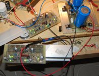
One is driving the dummy load to 100 watts, while the other amp sits idle and has the scope attached to the output. Hastily done, I should have shorted the input for it but here are the results:
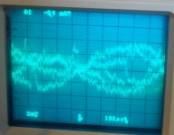
there is a lot of noise mixed in there from some source, could have a lot to do with all the wires flying and fluorescent lights. Anyway, looks to be about 8mVpp ripple (probe is on 1x, scope is at 2mV/div). Pretty darn good, I think.

One is driving the dummy load to 100 watts, while the other amp sits idle and has the scope attached to the output. Hastily done, I should have shorted the input for it but here are the results:

there is a lot of noise mixed in there from some source, could have a lot to do with all the wires flying and fluorescent lights. Anyway, looks to be about 8mVpp ripple (probe is on 1x, scope is at 2mV/div). Pretty darn good, I think.
Not happy with that last post so I re-did the test, this time with the input shorted. Looks a lot better:
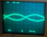
so, 4mVpp on the output with the other amp driving a 1k sinewave at 100 watts.
Looked at the positive rail of the idling amp:
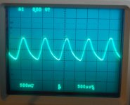
1Vpp ripple. Not bad for this supply, since it really isn't a 'regulator'. This is performance I can accept.

so, 4mVpp on the output with the other amp driving a 1k sinewave at 100 watts.
Looked at the positive rail of the idling amp:

1Vpp ripple. Not bad for this supply, since it really isn't a 'regulator'. This is performance I can accept.
Well I have a few questions and some ideas.
And, I don't know if there's merit to them; but, I figure you'll know. 🙂
Did you ac couple the heatsink to 0v or is it an antenna?
If the supply measures well with the input shorted (how the heck does it make power that way?) well then what about snubbing all of the diodes with small polyester capacitors and adding an RC across transformer secondaries?
Sure that's more typically seen on an unregulated tuner or transmitter power supply; however, Avoiding charging up huge caps on low-amperage noise, may have an effect. That effect might be decreased heat, but do you think the noise decrease would show on your scope?
Also, an RCR (3.3R, 3.3uF, 3.3R, aka economy grade polyester tweeter cap) at the output of the power supply board may get rid of noise before it can be amplified. When this is successful, the amplifier heatsink is at cooler average temperatures, which is very useful. But what I'm not sure about is whether this reduces noise in or noise out. So, the location of this may go at the input of the capacitive multiplier (cooler capmulti heatsink instead) rather than its output.
Well I have a few questions and some ideas.
And, I don't know if there's merit to them; but, I figure you'll know. 🙂
Did you ac couple the heatsink to 0v or is it an antenna?
Hi Dan,
The heatsink in the pic above is temporary, for testing. During the test it was grounded.
If the supply measures well with the input shorted (how the heck does it make power that way?) .
I should have been clearer in my explanation, I guess. I thought it would be obvious I was talking about the amps input being shorted, not the power supply. I sidetracked a bit there to look at the PSRR of the amp as it was powered with this supply.
well then what about snubbing all of the diodes with small polyester capacitors and adding an RC across transformer secondaries?
Sure that's more typically seen on an unregulated tuner or transmitter power supply; however, Avoiding charging up huge caps on low-amperage noise, may have an effect. That effect might be decreased heat, but do you think the noise decrease would show on your scope?
Effective snubbing happens with a correct RC values and it is difficult to determine the R value for this. The caps on their own can have some good effect, but not polyester - ceramic is a much better HF bypass cap. In this case, I chose to keep it simple and opted for bypass caps at the smoothing caps. These are 100nF ceramic.
Regarding noise. You need to pay attention to what you are looking at. Some of the scope pics are of the amplifier output, not the power supply. There is no discernible noise from the power supply. The open input of a high gain amplifier will pick up garbage from every nearby source, that is why I redid the PSRR test in post 132.
Also, an RCR (3.3R, 3.3uF, 3.3R, aka economy grade polyester tweeter cap) at the output of the power supply board may get rid of noise before it can be amplified.
Let's do some simple math, going with the supply in it's present state, at it's lower voltage:
50VDC rail driving an amp to 100 watts into an 8 ohm load will draw in excess of 3.5A(rms) current. Your two 3.3R resistors will drop more than 10VDC and needlessly consume ~35 watts!
We don't do thinks like that at Chaos 😉
Last edited:
Let's do some simple math, going with the supply in it's present state, at it's lower voltage:
50VDC rail driving an amp to 100 watts into an 8 ohm load will draw in excess of 3.5A(rms) current. Your two 3.3R resistors will drop more than 10VDC and needlessly consume ~35 watts!
We don't do thinks like that at Chaos 😉
The cap in the center of an "across the rails" RCR won't conduct DC, and if it does, then please replace that cap. 🙂 I'm sorry that your cap shorted out. You need a (one) 250v rated cap to safely go from V+ to V- across both 50vdc rails.
Reference for location of a single RCR (or a single high ESR polyester tweeter cap does the same job cheaper):
Post 116 illustrates DC outputs at C4,C6 for unregulated and R4-R10 for regulated DC.
These DC V+ to V- locations are prime candidates to turn extraneous AC into heat.
Some application notes: This single RCR doesn't connect to 0v. It doesn't consume DC power. It only consumes noise, including a little bit of the noise that comes from the speaker, back into the amplifier. Values given are only average values, so actual useful values may vary up to half or double (but not much farther).
This part is actually more useful strung between V+ and V- taps of the smaller electrolytic caps that are located upon the amplifier board of a monobloc. I actually use no resistors--only a high ESR polyester cap selected via ESR meter.
The cap in the center of an "across the rails" RCR won't conduct DC, and if it does, then please replace that cap. 🙂 I'm sorry that your cap shorted out. You need a (one) 250v rated cap to safely go from V+ to V- across both 50vdc rails.
Ah, I didn't get you before - you meant from rail to rail, not on each rail.
Fact is, at the final output of the regulator, AC is in the uV range and not an issue at all. To be honest, I prefer to spend my time fixing (and discussing) valid problems, rather than chasing ghosts.
Ah, I didn't get you before - you meant from rail to rail, not on each rail.
Fact is, at the final output of the regulator, AC is in the uV range and not an issue at all. To be honest, I prefer to spend my time fixing (and discussing) valid problems, rather than chasing ghosts.
Oh right. I was wondering if the location would be upon the unregulated portion of the supply, at C4,C6.
There its possible the RCR would simply give the regulator less work to do. That, plus snubbing the diodes, can prevent the big caps from charging up on low amperage noise signals, and thus better regulation (by about 1 volt). So, if that works right, it might also cool your power supply heatsink a bit.
Dan, perhaps you could do some practical experimentation and report back with your findings. I would be very interested to see what you come up with.
🙂
🙂
Yes sir, I've used those mods without exception. The lowered noise, is, of course, most noticeable at ear sensitivity peak, 2k with half as much noticeable at canal resonance of 4k.
Why? Oh, I like to jam out to a well culled selection of popular music in mp3 served up by computer and wish to make "sounds good loud" so that there's reduced blare sensation. Stress relief doesn't work when there's blare. And that reason is plenty good enough. But there's an additional effect of higher energy efficiency, demonstrated as less heat to heatsinks.
In your case, the amplifier that I had meant to chill out doesn't look like an amplifier and isn't doing any audio signal except for speaker return--I had meant to cool off your capmulti supply (its a biggie size current buffer) by giving it less work to do.
This is my fifth attempt to write a response, pretty much because of being a bit speechless.
I have three recent projects and one is regulated. The mods increase the capacity (decrease the heat) of transformers and heatsinks since there's less work to do--there's less unnecessary work to do.
So, I was trying to say, don't forget the simple, while you're focused on the complex. 🙂
When 1 or 2 volts of noise is expressed as a percentage against total voltage, you can see that the effective noise decrease is rather strong, since the noise in question has insufficient amperage, then approximately the same percentage of fluctuations is also eliminated. Fluctuations from noise on the power line getting rectified also appears as a kind of signal as the DC voltage bounces during workload and of course reducing that bounce also cuts off its unnecessary signal.
It seems that this will apply at the unregulated tap of your power supply and go into effect at the capmulti heatsink. Better defined input into the capmulti supply may only serve to reduce your power bills and have otherwise no audio effect--that's possible.
The cause of my long break was cleaner power into an (unregulated) amplifier that I had already built, resulting in the fact that the experience of true concert sound was as easy as flipping a pretty little chrome switch.
Its efficiency, as a proportion of watts out versus watts into its size of heatsink, is somewhat above 80%, and that's not bad for a Class AB amplifier. Unfortunately, I exploited that tolerance margin to run 4 ohm speakers, which isn't so efficient, but certainly does have nice dynamics, and this simplicity wiped out the need to create a higher voltage amplifier.
P.S.
In a really similar consideration, an active speaker without any passive crossover components Could, in theory, be somewhat similar to an active speaker with passive crossover components; but, the reality is astonishingly different.
- Status
- Not open for further replies.
- Home
- Amplifiers
- Solid State
- Patchwork 6: Power Supply Upgrade