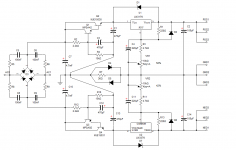
The front end supply? It should be able to supply up to 1A (bottleneck is the LM's), but that would be a bit counterproductive. It wasn't designed as a high current regulator.
The main supply (if it works 😀) could probably do 10A or more, depending on how many pass transistors it has.
Okey, might try that one for the main supply. We`ll see how much space there is left when im done with the amp 🙂
MJL 21193
I have now finished building the second power supply to the front end for Goldmund clone.
The first power supply I built on your PCB could easily be adjusted to my desired 2x80V DC. This was after I changed R2 (and R12) from 2.2 Kohm to 1.5 kOhm.
Power number two "acts" not that good.
I use the Variac transformer under test. With 230 V AC main, I can regulate the positive half, while the negative with LM 337 can not be regulated(?).
If I lower the voltage on the variable transformer so I can get 2x36 V AC into the PCB, I have no problems to vary both the positive and negative voltage from the power supply(?).
To match this power supply to my specific needs ,I think it is nessesary to calculated components different than your original with 2x48 V AC.
Changing only R2 is not "good" enough.
To do this, I need help, and hope that either you or Andrew might be able to assist. Andrew has been involved in a previous post, commented and given advice to this particular power supply.
Here are some measurements that might be useful to calculate the correct values of the individual components:
Voltage in on PCB: 2x71 V AC.
Voltage on C 7 / C 10: 2 x 97.3 V DC.
The desired voltage out from PCB: Adjustable down to 2x80 V DC.
Power out approx. 2x30mA
I want to get estimated R2/R3/R4.
When it comes to capacitors and diodes, I used what I had on hand.
They differ slightly from the original values. I reckon that these divergent are not crucial for the problems I mentioned earlier(?):
C7 = 2200uF/100V.
C1/2/3/4 = 220uF/100V
D1 = 1N 5259 (39V zener)
D2 / 4 = 1N5393
Transistors: As original.
Eivind Stillingen
Hi,
Change R2 to 1K, R3 to 6.8K and R4 to 22K. Do the same for the corresponding components on the negative side. This should give you ~93V at the base of Q1 and ~92V at the emitter of Q2.
Use regular diodes, like 1N4004, instead of the zeners (the 36V zeners are meant to protect the LMs from overvoltage).
Last edited:
Last edited:
Inspired by Liliya's efforts, I made some small changes to the layout, etched the board and populated it:
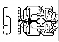
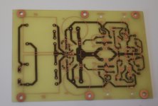
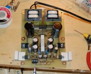
It works extremely well. Zero ripple (nothing that shows on the 2mV scale of my scope), even with a load drawing 200mA. Impressed, I am 🙂
The max I can get out of it with the transformers I used is ~56VDC which is as much as I need.
One problem I have right now is that the 2 large smoothing caps are 63V and the unloaded transformers are putting out ~80V, dropping to ~68V under load. Fine for testing but I need 100V caps for the permanent supply. It may be interesting to see how low I can make these caps before ripple appears. I'm thinking they could be as low as 1500uF.
John,
you can reduce the input caps to 470uF easily and use two 63V in series for the required 126V. They will fit in the space you used for the 4700uF. The reason I say this is that you already have a capacitance multiplier that will multiply the base capacitor by the gain of the Darlington.
you can reduce the input caps to 470uF easily and use two 63V in series for the required 126V. They will fit in the space you used for the 4700uF. The reason I say this is that you already have a capacitance multiplier that will multiply the base capacitor by the gain of the Darlington.
Nico I came this >< close to putting 470uF caps in there to begin with. The ones I have are 100V so 2 in series would not be needed. I'm going to try it with a load and see how much ripple I get.
MJL 21193
I have just finish front end power to both channels for my Goldmund clone with the changes you recommended in # 105, and it worked perfect.
I am looking forward to listen to the Goldmund with this latest changes later to night.
Your power unit, I think, will function way beyon the original voltage dopler.
Your measurements confirm my assumptions.
Eivind Stillingen
Nice to see it being used for something else 🙂
If I understand you correctly, you made two of these? One for each channel?
If I understand you correctly, you made two of these? One for each channel?
I'm going to try it with a load and see how much ripple I get.
Confirmed. With the 470uF caps in place, there is no discernible ripple on the scope. Supply is putting out 56V and driving a load to draw ~120mA. 120mA is the maximum front end current the 6 Patchwork amps can draw. Good times 🙂
I'm tempted to redo the board again to better suit the smaller caps but I don't think I will.
So, softstart and front end supply done. Next: main supply.
Main supply:
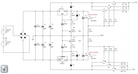
Pretty basic. It uses LM317/337 to pre-regulate plus the clean front end supply for the base drive of the pass devices. No feedback so it should be very stable.
I will use 3 pass transistors per rail and this should be adequate. Estimates put the minimum dissipation at around 6 watts per device at idle ( 6 amp modules consume 2A total at idle, pass devices drop ~16V) for total dissipation of 36 watts at idle.
At this time, I'm entertaining the idea of housing this part of the supply in a separate chassis. It really depends on how effectively the proposed heatsink performs and how hot it gets when driven hard. I'll need to build it as intended and use it to power the amps for testing.
Should be fun.
New plan.
I've decided to do 2 main supplies, one for the right channel and one for the left, rather than run all six amps from one supply.
I've also simplified the circuit somewhat by eliminating the use of the front end supply:
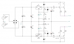
Should be nearly as good but the shortcoming will be made up for by the fact that it will now be 2 supplies as opposed to one.
They will each use 4 pass devices, for a total of eight. I'm thinking about using the MJW21195/96, which are a bit smaller than the MJL21193/94 but should be up for job. I have enough of these and no other use for them at this time.
I've decided to do 2 main supplies, one for the right channel and one for the left, rather than run all six amps from one supply.
I've also simplified the circuit somewhat by eliminating the use of the front end supply:

Should be nearly as good but the shortcoming will be made up for by the fact that it will now be 2 supplies as opposed to one.
They will each use 4 pass devices, for a total of eight. I'm thinking about using the MJW21195/96, which are a bit smaller than the MJL21193/94 but should be up for job. I have enough of these and no other use for them at this time.
New plan.
I've decided to do 2 main supplies, one for the right channel and one for the left, rather than run all six amps from one supply.
I've also simplified the circuit somewhat by eliminating the use of the front end supply:
View attachment 211211
Should be nearly as good but the shortcoming will be made up for by the fact that it will now be 2 supplies as opposed to one.
They will each use 4 pass devices, for a total of eight. I'm thinking about using the MJW21195/96, which are a bit smaller than the MJL21193/94 but should be up for job. I have enough of these and no other use for them at this time.
SO HOW IS YOUR BEAST PROGRESSING?
Have you done any tests. If you PSU current capability exceeds the current requirement by even 10 % you will never clip if you design amps like me, there will be plenty headroom for those sudden peaks.
It is nice to have someone follow similar objectives as oneself as I can predict what the patchwork amp will sound like with a rock steady low output impedance power supply with zero ripple.
Nico
Hi John,
this is not to degrade your design at all but a possible alternative to using the LM regulators. This supply integrated both regulator and capacitance multiplier into the design - which is what I am using on my current amplifiers. I do not drop a large voltage across it so the supply can be made to drive loads of several amps. Mine is ten amp per rail.
The analysis shows a contact closing for 20 mS drawing a high current pulse and see the effect on both regulated and un regulated supply lines.
If you have any interest in looking at some of it you are most welcome. I have PCB plots for it as well.
Attachments
SO HOW IS YOUR BEAST PROGRESSING?
Hey Nico,
I have a board layout for the main supplies nearly done:
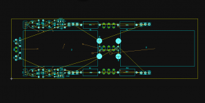
But these definitely won't fit in the existing case. I'm re-examining my options.
One is to build a separate unit to house the power supply (as you suggested earlier). One rather large problem with this is feeding the power from one box to the other and this is what I don't like about it.
Another, kind of extreme idea, is to build an entirely new chassis. One that is about 50% bigger and use the original one for the centre channel (active 2-way) and rear surrounds (active 2-ways). This actually is more appealing to me, as I had every intention of building another 6 channel for this purpose.
So, that is the working plan at this time. Leave the original 6 channel as is and construct a completely new 6 channel. I think I'll use my Abomination amps for this one. 😀
This supply integrated both regulator and capacitance multiplier into the design
Thanks Nico, looks good - making me think and giving me ideas. No issues using a cap multiplier with an AB amp? I understood that it was not suitable for that. Seems you have excellent transient response, so that answers that question. 🙂
You know me, nothing is written in stone until it's written in stone (or wood and metal) 😉
Probably one of the last posts in this thread, as I'll be starting another covering the new 6 channel amp build.
Re-did the layout for the main supply, having the big caps standing upright, rather than laying down:
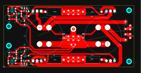
I probably could have done a better job and may do some further tinkering with it but for now I'll etch this one to see how it performs.
Re-did the layout for the main supply, having the big caps standing upright, rather than laying down:

I probably could have done a better job and may do some further tinkering with it but for now I'll etch this one to see how it performs.
- Status
- Not open for further replies.
- Home
- Amplifiers
- Solid State
- Patchwork 6: Power Supply Upgrade
