Nice. I thought about using ordinary FETs to pull down the input but wasn't sure just how much distortion they would add. It looks like those VCR2Ns would be a great option.
They don't seem to be readily available though - I checked Digikey and Mouser and not in stock. Looks like they'll soon be obsolete.
They don't seem to be readily available though - I checked Digikey and Mouser and not in stock. Looks like they'll soon be obsolete.
Also try RS Components International for component supply and there is also Farnell / Electronic Component Distributors / Suppliers / Electronics, Electrical Parts, Electrical Components and Wholesale Electronics. for those hard to get stuff
H11f1 "m" opto
Only a $1.88 @ mouser and the solution for my preamp input switcher. THX , nico. I didn't know they made these. (H11f1 "M") 😱
OS
Sorry
Only a $1.88 @ mouser and the solution for my preamp input switcher. THX , nico. I didn't know they made these. (H11f1 "M") 😱
OS
Last edited:
Good to have options, for sure. At this time though, I will stay with the relays. One excellent reason is that I already have them. I have had them for about 5 years and not found a use for them, other than one or 2. Another good reason is that I just blew my DIY budget on those big caps and can't justify yet another parts order. Finally, I like relays, especially when there is more than one lined up - they look cool. 
Yeah, I'm surely going nuts...

Yeah, I'm surely going nuts...
Member
Joined 2009
Paid Member
I'm thinking a nice thing about the relays, if they're SPDT is that you can arrange for them to be normally closed when there's no power to them - this way the output is fail-safe shunted to ground (if a shorted output is every considered 'safe'!) in the absence of power.
The intended configuration for the relays on the outputs is normally open, cutting off output to the speakers. Only when the amp is powered up and after a ~3 second delay do the relays close, connecting the outputs to the speakers.
It's unfortunate that the relays I have are SPDT and not DPDT - I could then use half the total number of relays (6 as opposed to 12). This would be great for the inputs, where all of the relays would be in one place.For the outputs, not so good - with 3 amps on either side of the case, it would be better to have 3 and 3 for relays as well.
Anyway, I will probably start board layout, making and testing soon of the various bits and pieces. First will be the all-new softstart.
Soft start:
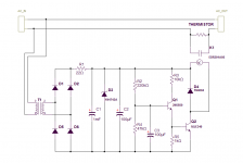
Simple and fairly cheap, the only thing I had to buy for it was the transformer and that was only $3.50. It operates in the same way as the one I'm using now, the difference being that it uses a separate transformer on board instead off tapping of the positive rail of the main supply. This makes it self contained, with just 2 wires in and 2 wires out.
The board layout:
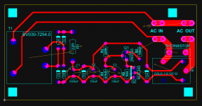
Fairly compact at 6cm x 12cm. The relays I have are a standard footprint for miniature SPDT. I would prefer to have a bit more space between the coil terminal and the hot terminal of the relay but since the board is isolated from the secondary side, I'm not worried about it.
I'll see if I have time tomorrow to make this board and test it out.

Simple and fairly cheap, the only thing I had to buy for it was the transformer and that was only $3.50. It operates in the same way as the one I'm using now, the difference being that it uses a separate transformer on board instead off tapping of the positive rail of the main supply. This makes it self contained, with just 2 wires in and 2 wires out.
The board layout:

Fairly compact at 6cm x 12cm. The relays I have are a standard footprint for miniature SPDT. I would prefer to have a bit more space between the coil terminal and the hot terminal of the relay but since the board is isolated from the secondary side, I'm not worried about it.
I'll see if I have time tomorrow to make this board and test it out.
Hi
I don't know your Zener voltage.
Resistor values for R3, 4 & 5 seem odd.
Is the To126 Q2 saturated when "ON"?
Does R3 pass sufficient current to satisfy Base current demand of Q2 and feed R5.
Why is R4 there?
Why is C1 there?
Excellent points Andrew and thanks for looking.
The zener (1N4742A) is 12V.
You are correct about R3, it is not providing enough current. When I changed the circuit to operate on 12V (as opposed to 56V), I reduced R3 but but not enough. Thanks for bringing it to my attention.
R4, strictly speaking, is not needed but I thought it would help to drain C3 when power is cut and keep it from building a residual charge when the amp is unpowered. Another look tells me that this is not the case and I will remove it.
C1 smooths the supply ripple. Rationale: maybe the relay will buzz if there is too much supply ripple. I'm not sure yet if it is needed or not, but since it is not a major difference to the cost of the circuit, I'll leave it in.
New schematic:
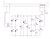

You have C2=100uF and C1=1mF
Choose one value and discard the other.
A relay pulls in @ ~80% of rated voltage.
It will not drop out until the supply drops to ~20% of rated voltage.
A bit, or even a lot, of ripple will not cause the relay to momentarily drop out (buzz).
What you might get is a stronger/weaker pull on the armature and this may cause a bending motion similar to a vibration. This will continuously micro wipe the contacts. I don't know how low the voltage would need to fall for this effect to occur.
Last edited:
Dammit Andrew! How do you spot these things? 
Yes, I'll chop C2.
This is the value of another pair of eyes, it reveals things that are hidden in plain sight to the 'designer'.
Thanks again, Andrew. 🙂

Yes, I'll chop C2.
This is the value of another pair of eyes, it reveals things that are hidden in plain sight to the 'designer'.
Thanks again, Andrew. 🙂
Yes, It can be of great benefit to have someone looking over your shoulder. Glad you take the time to look in Andrew. 🙂
New schematic:

and with the changes, I was able to make the board a full cm shorter!
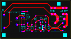
I did forget on important item that needs to be on this board: the main fuse. I ease that in shortly but won't bother with posting a new layout.
New schematic:

and with the changes, I was able to make the board a full cm shorter!

I did forget on important item that needs to be on this board: the main fuse. I ease that in shortly but won't bother with posting a new layout.
Soft start is built:
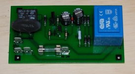
New look. One small issue - the AC in faston is a little too close to the fuse holder. No big deal, I can still get the connector on.
Testing:
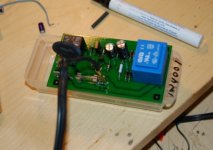
There is roughly a 2 second delay before the relay closes and it instantly opens when the power is cut off. Seems to work fine and no buzz from the relay.

New look. One small issue - the AC in faston is a little too close to the fuse holder. No big deal, I can still get the connector on.
Testing:

There is roughly a 2 second delay before the relay closes and it instantly opens when the power is cut off. Seems to work fine and no buzz from the relay.
Hello, MJL 21193.
I am looking for stabilized power for the front end to my Golmund clone.
I intend to use ca.2x64V AC in order to get 2x80 V DC. Can I use your diagram
without any changes?? If changes has to be done, what????
I will take into account that Capacitors must withstand higher voltages than what you use. By the way, witch one need to be high voltage (100V)?
Transitors you use will endure well the above voltage.
Are you willing to post your print layout, so I can copy it and make
these myselves.
Regards
Eivind Stillingen
Last edited:
Hi,
I haven't prototyped and tested that board yet, so use it at your own risk.
View attachment FES_CB.zip
All of the caps would need to be 100V. Also, the board is laid out for the transformers I bought: Digi-Key - MT2232-ND (Manufacturer - 3FS-548)
and it's doubtful another would fit.
I haven't prototyped and tested that board yet, so use it at your own risk.
View attachment FES_CB.zip
All of the caps would need to be 100V. Also, the board is laid out for the transformers I bought: Digi-Key - MT2232-ND (Manufacturer - 3FS-548)
and it's doubtful another would fit.
- Status
- Not open for further replies.
- Home
- Amplifiers
- Solid State
- Patchwork 6: Power Supply Upgrade