Does this mean the zener and the smd JFETs should be upgraded with 30v or more parts? More coffee needed.
no reason to change neither value nor power of zeners used
with normal use and procedures, nothing wrong will happen
zener is there to cover mishaps and possible power-on transients, in case someone get to different cap values (before and after series CCS)
and, this time, I can bet it did what's placed for - JFet is still alive
again, who knows what zap you made, while having things wrongly connected
OK 🙏
The JFet's all measure about 120R D-to-S so maybe I am in luck. Will try a new zener later in the AM, and fire it up connected correctly to the load.
The JFet's all measure about 120R D-to-S so maybe I am in luck. Will try a new zener later in the AM, and fire it up connected correctly to the load.

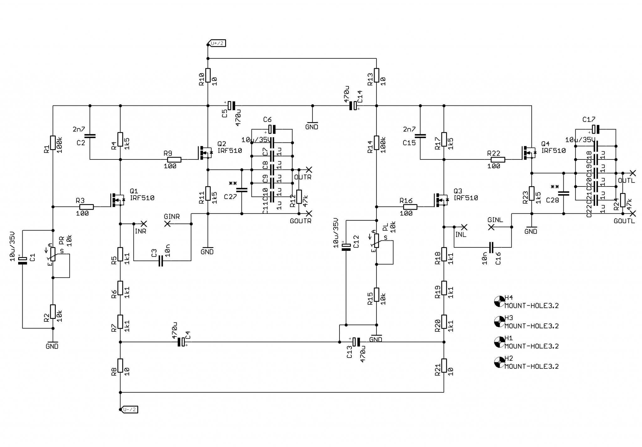
Quick/beginner question. I understand R4/R17 are the IV resistors of D1, but in addition to these two, would R9 and R11 be considered in the signal path?
R9 is gate stopper, of course that it is in signal path
though, if you enjoy being anal, chasing "better than proper industrial metal film", be my guest
R11 is practically load for Q2 source follower; final element where current swing being converted to voltage swing, so - yes - it is in signal path
again what I wrote in second line
though, if you enjoy being anal, chasing "better than proper industrial metal film", be my guest
R11 is practically load for Q2 source follower; final element where current swing being converted to voltage swing, so - yes - it is in signal path
again what I wrote in second line
Thanks ZM. If you ask my family, I was born anal 😂
Just curious/learning. I am playing with different DAC chips and resistors are not in focus at the moment.
Just curious/learning. I am playing with different DAC chips and resistors are not in focus at the moment.
Another question...
For the beautiful array of 'output' capacitors, is the role DC blocking, and is the value (15uF) selected to have appropriately low roll off in the context of the preamp input impedance?
Cheers -

For the beautiful array of 'output' capacitors, is the role DC blocking, and is the value (15uF) selected to have appropriately low roll off in the context of the preamp input impedance?
Cheers -
I already wrote about that:
- have drekload of Philips MKC
- have enough nice 10uF elcos
- they look nice that way
- put them plenty, no need to waste battery in Casio calc
Thanks ZM. I can be a bit dense...
You must have anticipated the next question.
So, going into a 50k input impedance preamp, if I get it right, the -3db roll off is about 0.2 hz. At some point, I gathered some 1uF caps for DC blocking in a tube DAC and I was just wondering if it might be worth trying them in the D1, if/when I get bored. It seems, 1 uF would give a 3.2 hz -3db roll off. Now my Casio is limited to very basic functions and I may have this all wrong.
And not asking you to bust out your calculator..
Cheers,
Soren
F=1/(2*Pi*R*C)
just play with it ...... I'm not loosing my sleep thinking of better cap than combo made of polycarbonate + industrial quality elco
find your fave and stay stubbornly with that ....... waste your energy on other things
just play with it ...... I'm not loosing my sleep thinking of better cap than combo made of polycarbonate + industrial quality elco
find your fave and stay stubbornly with that ....... waste your energy on other things
Good news for Threshold DAC-2 owner's:
go to post #21 under
go to post #21 under
Thank you very much Mr. Wu for providing the module. Very regret. The module is damaged. Mr. Wu kept it for 13 years, and now he has given it to me. I think I can fix him. But I'm very sorry, what he damaged was the main control chip OKI M72H035. I cannot purchase him from all over the world. I searched the whole world. No one is selling. So I made an IIS signal generator. I want to test the generation of the problem. After careful testing. Discovered that the right channel BIT17 has been at a high level for a long time. Cannot switch. I think M72H035 is completely irreparable. I want to...
- wyqgyn
- Replies: 24
- Forum: Vendor's Bazaar
@zm, thanks very much for the files and background, I have a populated board ready to go, two questions:here's what I can give, from my old files
1) what's the procedure to adjust offset?
2) I will power the board w/ UltraBiB 1.3 shunt regulators. Is 30V to power the D1 good?
The only curious thing about firing this up, is that you measure and adjust DC offset on the INPUT.
Fed it +/- 30V and let it cook for 20 min without the DAC chip connected to the input. Measure offset on the inputs and adjust. Once you are happy, connect the DAC output and enjoy.
If bypassing the on board PSU, you can always study my photos for how not to connect it 😊
Fed it +/- 30V and let it cook for 20 min without the DAC chip connected to the input. Measure offset on the inputs and adjust. Once you are happy, connect the DAC output and enjoy.
If bypassing the on board PSU, you can always study my photos for how not to connect it 😊
if you increase R4 from 1K5 to 1K8, it'll give you 1.8/1.5 increase of output swing
in any case, don't go above 2K
change R11 downward in value by same ratio; so, if going with R4 to 1K8, change R11 to 1K2 (nearest standard value); that for keeping output source follower current on same level
be sure to check/reset DC level at input node after any change
in any case, don't go above 2K
change R11 downward in value by same ratio; so, if going with R4 to 1K8, change R11 to 1K2 (nearest standard value); that for keeping output source follower current on same level
be sure to check/reset DC level at input node after any change
@Zen Mod - per your schematic, to increase gain not only should change R4 (1k5 to 1k8) and R11 (1k5 to 1k2), but also R17 and R23?
Do I have that right?
Thanks very much.
gain increase is with R4 (one phase/channel) and R17 (second phase/channel)
decreasing value of R11 (one phase/channel source follower) and R23 (second phase/channel source follower) is having nothing with gain, "just" keeping Iq of follower at same value
decreasing value of R11 (one phase/channel source follower) and R23 (second phase/channel source follower) is having nothing with gain, "just" keeping Iq of follower at same value

- Home
- Amplifiers
- Pass Labs
- Passlabs D1 (PCM63) vs. Threshold DAC-2 (Ultra Analog D20400a) - who have heard both?