Don't know if you've already bought the switch, but if not, switching signal grounds as well is the better way to go. Of course, you have to use RCA's that are isolated if you're going to this.
AndrewT, could you please explain what is wrong with the volume control?
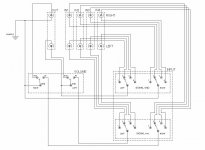
I've included switched signal references/grounds now. Also, after re-reading DF96's post more carefully I've connected the chassis to the right channel's signal ground.
If I have a problem with the chassis only connected to the right channel, it'll be easy for me to run a short wire from the chassis ground pin to the left channel's signal ground circuit.
If I can just get to the bottom of the problem with my voume control arrangement I'd say this design is finished now.
Cheers guys,
Leon
Attachments
You have Signal Return connected to switch Common.
In the left position "out" is connected to Signal Return. You have shorted the input of the next item in the receiving chain.
In the right position "in" is connected to Signal Return. You have shorted the selected input of the previous item's "output" to Signal Return. Will the transmitter device survive a short?
In a Switched attenuator Switch Common is equivalent to Wiper.
swap it around.
Last edited:

What is the point in posting a schematic that you know is wrong and then asking Members to comment and comment and explain their comment?
To ask for help and advice. Why else?
I didn't know the schematic was wrong. I posted it on here to ask for advice as I'm very inexperienced in electronics: this is my very first attempt at making anything with a soldering iron. I got the help and advice I needed, for which I'm very grateful, and now the schematic is correct.
Given that all of the above is obvious I can only read your question as rhetorical, and therefore patronising and slightly insulting.
I really hope that I've misconstrued your question, since you have been most helpful and it'd be a shame to end our conversation on a sour note.
Regards,
Leon
For the volume control I'm custom-making a series type stepped attenuator from a twin-layer, 2 pole, 24 way elma rotary switch and a selection of takman 1% resistors.
Hi Leon, if you haven't already bought the switch, make sure it is a make before break type before you do 🙂 I tried to make my own crude stepped attenuator many years ago (before I knew that such a thing existed, I thought I was being smart and had finally thought of a way to get around the woeful channel differences with the cheap pots I had access to).
However as my prototype I used a standard rotary 6 position switch, and when combined with a certain amount of DC on the output of the buffer from my input selection, I got VERY loud pops out of the speaker each time the switch was rotated to the next position. I scrapped the idea, and it wasn't until many years later I discovered that I was on the right track but just didn't have the right type of switch. Using a make before break switch will stop the pops.
Tony.
Tony,
No I haven't bought any parts yet. But yes I'm aware that I need a make-before-break (shorting) switch for the volume control, and a break-before-make (non-shorting) switch for the input selector.
Thanks for your advice all the same.
Leon
No I haven't bought any parts yet. But yes I'm aware that I need a make-before-break (shorting) switch for the volume control, and a break-before-make (non-shorting) switch for the input selector.
Thanks for your advice all the same.
Leon
It was not rhetorical.
I am extremely displeased that you drew the attenuator incorrectly and now say you didn't know it was wrong.
The schematic being incorrect is excusable. That was the whole point of your initial post.
The comment
I am extremely displeased that you drew the attenuator incorrectly and now say you didn't know it was wrong.
The schematic being incorrect is excusable. That was the whole point of your initial post.
The comment
Given that all of the above is obvious I can only read your question as rhetorical, and therefore patronising and slightly insulting{/quote]seems to allude to your knowing you have drawn the attenuator wrongly and you discard that crucial point as if it does not matter.
This ends in a very sour note.
Unfortunately we can't read your intentions. Once we get to know someone, we may be able to guess which of his mistakes are random errors (which we all make) and which are the result of significant misunderstanding of the technology. Until then, we assume that someone means what he says/writes. Your comment sounds like you are claiming that you are not really as wrong as you appear to be. A simple apology might have been better.The Boz said:Ah I see what you're saying. I'd drawn it wrong, but my intentions were correct.
However
looks like over-reaction.AndrewT said:I am extremely displeased . . . The schematic being incorrect is excusable.
Can we all calm down?
Jeez guys, I got the GND and OUT the wrong way round. Talk about a mountain out of a mole hill.
And you're "extremely displeased" I didn't know it was wrong? Are you kidding? Why would I intentionally draw it wrong? And then start a thread asking whether what I've drawn is right, knowing full well it isn't and even what specifically is wrong with it? That would just be a massive waste of everyone's time, including my own.
When I said "given that all of the above is obvious...", I was referring to:
"I didn't know the schematic was wrong. I posted it on here to ask for advice as I'm very inexperienced in electronics"
Anyway this has gotten a bit ridiculous now. I got the GND and OUT mixed up. Big deal. Thanks for your help in putting it right.
Leon
- Status
- Not open for further replies.
- Home
- Source & Line
- Analog Line Level
- Passive Preamp - Grounding plan