I am planning to build a PLLXO 24dB slope Linkwitz-Riley. That would be Marchand style caps and chokes affair. I have no experience in this and am desperately looking for schematics, calculators, component brand names (inductors). To start I want to build a 100Hz Low pass filter. Any help will be appreciated.
Linkwitz-Riley described an *active* R-C-opamp plan. (Yes, any active plan has an equivalent L-C-R plan.)
"PLLXO" is described on this page. Note that these are all R-C (no L). Note that no 24dB/oct plan is covered. Such a thing is possible, if you have a huge ratio of source to load, and accept a VERY gradual slope (Q<<1).
A "good" 24dB/oct passive filter will need chokes. That calculations are do-able; I strongly endorse Lancaster's Active Filter Cookbook (it starts from L-C-R to get to active filter theory).
A Q=~~1 L-C-R filter "can" be designed off a Reactance Chart (a forgotten but very useful tool).
Pick 100Hz. Pick an impedance. Too low will load-down your source, too high (in audio) leads to unlikely L values. With a bit of poking and some past experience, assuming an opamp is driving this, I pick 1K nominal impedance.
From the Reactance Chart, 100Hz and 1K resistance cross at 1.6 Henries and 1.6uFd. These values and a couple 1K resistors leads to a 100Hz low-pass, but the actual response (both amplitude and in/out impedances!) is hard to verify without deep understanding.
There ARE loudspeaker crossover calculators. It is nearly the same problem. We assume a low source impedance and a specific near-resistive load. First problem is that these tools may not believe in load (speaker) impedance as high as 1K. Here's one:
ERSE - Crossover Calculator - Fourth Order 2 Way
The fix is to tell it you have a 10r speaker, then take the values it gives and scale 100X up (for L) and 100X down (for C).
This calculator is giving values somewhat apart from the 1.6H and 1.6uFd taken from the Reactance Chart. It may be right: cascading two sections is much interaction and the values must shift.
IAC: 1H-3H chokes are a big problem. That is mighty high for air-core. Iron-core chokes is a whole field of calculations and experimentation. True, a cheap table-radio OT may be in this area. For some specific drive level. The inductance WILL change as level changes. Perhaps a better path is like a Hammond 125ESE, which runs near 9H stock and is gapped. Pry the mount apart, pry the gap, and put a few more sheets of paper in. Clamp tight and measure. It will come down to a lower H. The now-large air-gap will stabilize inductance shift. But that is a $69 part, and I'll guess you don't see an easy way to measure such large inductances at 100Hz (it will be different at 1KHz of generic coil testers).
Attachments
Here's another calculator that has no trouble accepting 1k as the 'bass/mid' impedance.
Passive Crossover Design Equations Formulas Calculator - Two Way Fourth Order Network Gaussian Linear Phase Butterworth Legendre
Inductor values come out as 1.5H and 3H, massive for Marchand-style inductors which if I recall correctly are gapped ferrite cores.
One solution would be to use a transformer at the input to go from a high to lower impedance, then another at the output to step up once again (or use an active gain stage). A 4:1 step down will render the inductors 16X smaller which I reckon is quite do-able with gapped ferrites (188mH, 94mH).
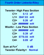
While abraxalito was posting a better tool, I beat my Idiot Assistant to verify/refute my hasty-calc and the ERSE calc (with 100X transposition).
The ERSE is quite correct. The hasty-calc leads (as expected) to a very approximate not-good result, with wrong response and wacky input impedance.
The ERSE is quite correct. The hasty-calc leads (as expected) to a very approximate not-good result, with wrong response and wacky input impedance.
Attachments
You can pretty much use text book forumlas, Marchand terminates theirs (ie loads the LCs with a 5k R. This makes for a load that is a bit hard to drive, but makes the already hard to source Ls, smaller.
dave
dave
Thanks everybody for the quick and informative response.
@PRR.
The ERSE calculator is very useful. How did you generate the response
curves? Is this part of ERSE? Would you be so kind as to generate curves for
130Hz and 160Hz as the 100Hz one seems a bit too quick to fall for my needs.
I forgot LR 24dB filter is already 6dB down at the 100Hz.
@planet10
I am good with my hands and ears, not so much with maths and formulas.
My source is 75 Ohm DAC output after which there is a passive attenuator (DACT 10k).
Then the signal splits into mains amps (passive XO in the speakers) and sub amps.
The latter would be preceded by the Low Pass PLLXO. The amps are hypex ncore with 50k impedance.
Is the schematics generated by PRR with ERSE compatible with my setup?
Or you are suggesting some changes along the Marchand line? What would that be then, what components
added and where in the circuit?Marchand XM46 says 1k input typical and 10kOhm output min.
TIA to all again.
Last edited:
I think that the passive attenuator could kill your ability to drive the OLLXO if it is terminated with an R as low as Marchand uses, and a higher terminating R is going to push the sizes of the inductors into the stratosphere.
What are your amplifier input impedances? You cannot go higher than that for terminating R.
The XO will be pretty much a textbook one given the very resistive load.
I have attached the output of the Bagby calculator with 130 Hz and 5k load impedance. I can’t change column of font size, so 2 of th einductor values are unknown except that they exceed 10F.
dave
Attachments
I think that the passive attenuator could kill your ability to drive the OLLXO if it is terminated with an R as low as Marchand uses, and a higher terminating R is going to push the sizes of the inductors into the stratosphere.
What are your amplifier input impedances? You cannot go higher than that for terminating R.
The XO will be pretty much a textbook one given the very resistive load.
I have attached the output of the Bagby calculator with 130 Hz and 5k load impedance. I can’t change column of font size, so 2 of the inductor values are unknown except that they exceed 10F.
dave
The sub amps are d-class with input impedances 50 kOhm.
The inductor values you mention would exceed 10 HENRIES, not farads, right?
Right Henries. Looked wrong when i typed it. If you used the input impedance of your amp indictors would need to be 10x larger, caps 1/10th
dave
dave
Please forgive my ignorance here, but could you clarify? If my amps are 50kOhm input then what values should inductors and caps have? Marchand's XM46 rated output is 10kOhm min. and I read somewhere their low pass inductors are in 1--3 henries range.Right Henries. Looked wrong when i typed it. If you used the input impedance of your amp indictors would need to be 10x larger, caps 1/10th
dave
If Marchand’s XOs use a 5k termination — that info is old, but from corespondence with Marchand, then the calculations for a text book LR filter should be as i posted earlier. Change the output load the values change in a coresponding manner. No magic.
The Marchands have a fixed R loading the filter, which is in parallel with the input impedance of your amplifier… hopefully high enuff that it is not significant (otherwise they’d have to make each XO custom.
dave
The Marchands have a fixed R loading the filter, which is in parallel with the input impedance of your amplifier… hopefully high enuff that it is not significant (otherwise they’d have to make each XO custom.
dave
... generate curves for 130Hz and 160Hz as the 100Hz one seems a bit too quick to fall for my needs. ...
I submit that a 4-pole filter has almost no business being in the audio band. Yes, subwoofer "squawk" may be a reason. But for many reasons, IMHO you should be thinking 3-pole.
Moving the frequency is just reducing the inductance and capacitance by the same ratio. Same curve, shifted over.
OH: I believe the curve I posted has a typo. The Red curve really should be -3dB @ 100Hz. I may have posted a flawed run.
Last edited:
...IMHO you should be thinking 3-pole.
I won’t disagree with that.
dave
- Status
- Not open for further replies.
- Home
- Source & Line
- Analog Line Level
- passive line level XO 4th order how to