Here's a simple design tool for L-C audio filters from 1949.
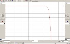
I started plotting a 30hz filter. (3-pole, so only 18dB/Oct; but these filters can be cascaded until you run out of money.)
Hi-Fi interface is nominal 10K. Plot that. Argh! 100 Henries is a mighty big choke.
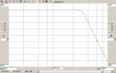
Modern Hi-Fi will pull 600 Ohms comfortably. This plots to like 6 Henries, big but not impractical. Go to the other chart, we get 20uFd, quite practical.
To use this design in Hi-Fi interface you need to pad-out the source to 600 Ohms (probably an added 470r resistor) and load the output to 600r (620r shunt).
The article is over-simplified. He does mention choke resistance but not "how much is bad". Later he calculates 6Kcps at 100K and comes up with a large 5H choke and 275uuF.... but a 5H choke is liable to have a hundred pFd end-to-end and end-to ground, needing a large practical correction and probably gross error of response.
Still a handy tool to start putting numbers in a net-analyzer or computer simulation.
I started plotting a 30hz filter. (3-pole, so only 18dB/Oct; but these filters can be cascaded until you run out of money.)
Hi-Fi interface is nominal 10K. Plot that. Argh! 100 Henries is a mighty big choke.
Modern Hi-Fi will pull 600 Ohms comfortably. This plots to like 6 Henries, big but not impractical. Go to the other chart, we get 20uFd, quite practical.
To use this design in Hi-Fi interface you need to pad-out the source to 600 Ohms (probably an added 470r resistor) and load the output to 600r (620r shunt).
The article is over-simplified. He does mention choke resistance but not "how much is bad". Later he calculates 6Kcps at 100K and comes up with a large 5H choke and 275uuF.... but a 5H choke is liable to have a hundred pFd end-to-end and end-to ground, needing a large practical correction and probably gross error of response.
Still a handy tool to start putting numbers in a net-analyzer or computer simulation.
Attachments

You can connect two 24dB/oct sections together back-to-back, but you won't get the same result as a properly designed 48dB/oct filter (8 poles).
The attached schematic has a cutoff freq of 30.7Hz and a stop band of 47.9dB at 60.7Hz. The resistors should be 1% and the caps 5% or better. The really critical stage is the last one and you may need to tweak the cap values to prevent peaking at the corner freq.
The attached schematic has a cutoff freq of 30.7Hz and a stop band of 47.9dB at 60.7Hz. The resistors should be 1% and the caps 5% or better. The really critical stage is the last one and you may need to tweak the cap values to prevent peaking at the corner freq.
Attachments
- Status
- Not open for further replies.