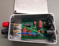
For those who may be curious, I simulated and built this 20kHz brickwall filter in a little case. Parts were series/paralleled and inductors unwound to get close to exact values.
I quickly tested it and it seems pretty good, better than the earlier RC based one I used.
(original thread closed but here)
https://www.diyaudio.com/community/...r-for-class-d-amp-testing.277076/post-4390598
I quickly tested it and it seems pretty good, better than the earlier RC based one I used.
(original thread closed but here)
https://www.diyaudio.com/community/...r-for-class-d-amp-testing.277076/post-4390598
Attachments
Last edited:

Do you measured? I ask because only the brick filter does not seem to be, taking into account that we are talking about relatively high frequencies at which capacitive and inductive couplings are very easily achieved and its efficiency drops dramatically because of them.
A filter that can be called that and be effective at frequencies of hundreds of kilohertz must be made in several stages, each one individually shielded.
A filter that can be called that and be effective at frequencies of hundreds of kilohertz must be made in several stages, each one individually shielded.
Measurements of the full performance will need equipment I only have at my office but will do it at some stage.
Yours is of course a very valid point: no filter is anyway 'brickwall' across the frequency spectrum. To have improved it would have been large and expensive with PTFE PCBs and expensive parts. But this is not the goal since the ADC in the measurement device already has an analog active input filter/buffer with F3 far below 1MHz. The AES17 filter assists with removing the large residual switching harmonics from the amplifier output (which usually only has a 2-pole LC demodulation filter) that would overload the ADC input filter and distort the measurements.
Overall though I'm sure this filter is not a precision lab device for writing datasheets but merely to improve measurement results as it certainly is not perfect but also does not have to be. Having said that, this is what inspired me to build my filter:
https://www.itsonlyaudio.com/web-shop/ap-system-onetwo-brick-wall-filter/
Nice build, but for low level THD air core inductors are required.For those who may be curious, I simulated and built this 20kHz brickwall filter in a little case. Parts were series/paralleled and inductors unwound to get close to exact values.
I quickly tested it and it seems pretty good, better than the earlier RC based one I used.
(original thread closed but here)
https://www.diyaudio.com/community/...r-for-class-d-amp-testing.277076/post-4390598
Do you have some THD measurment of your filter?
Martin
I designed the AUX-0025 filter when I was @ Audio Precision. Back then the Class D amplifiers usually had a lot of carrier output junk. The carrier signal presents, lead to IM products on the input stages of the Audio Analyzers.
The use of a AES17 filter only keeps frequencies above the audio band from going into the ADC as it is installed long after in input stages.
By reading the full file you may gain more information about this filter and its usage.
Duke
https://www.diyaudio.com/community/...r-for-class-d-amp-testing.277076/post-4390598
DIY measurement system usually contains some audio ADC/interface with 2-3Vrms 0dbfs, hence, some resistor divider would involve scaling 20-30Vrms amp's output to that ADC max input voltage. In that case, implementing the LPF at the low-voltage site would be easier.
You can use compact and cheap industrial coils on the ferrite core(BTW, low-sensitive to EMI), as well as low voltage C0G/NP0 caps and get -130-140db of the H3.
You can use compact and cheap industrial coils on the ferrite core(BTW, low-sensitive to EMI), as well as low voltage C0G/NP0 caps and get -130-140db of the H3.
Hi Duke, I used that filter 2005-2007 while doing postgrad FPGA-based Class D experiments! Never opened it up but was always curious of the insides.I designed the AUX-0025 filter when I was @ Audio Precision. Back then the Class D amplifiers usually had a lot of carrier output junk. The carrier signal presents, lead to IM products on the input stages of the Audio Analyzers.
The use of a AES17 filter only keeps frequencies above the audio band from going into the ADC as it is installed long after in input stages.
By reading the full file you may gain more information about this filter and its usage.
Duke
https://www.diyaudio.com/community/...r-for-class-d-amp-testing.277076/post-4390598
Pierre
- Home
- Design & Build
- Equipment & Tools
- Passive Filter for Class D Amp Testing - built