So it seems pretty well-established at this point that a parallel LCR in series with a driver (as opposed to a series LCR in parallel with a driver) can function to suppress any extra HD from the increased sensitivity around breakup (and, I guess, HD-driven IMD too).
But, can a typical passive low-pass filter do the exact same thing, e.g. 2nd order LR or 4th order LR, as long as the slope starts early enough that there is significant attenuation around the peak?
But, can a typical passive low-pass filter do the exact same thing, e.g. 2nd order LR or 4th order LR, as long as the slope starts early enough that there is significant attenuation around the peak?
A notch filter, whether series or parallel, returns to passing the signal without filtering above the notch. A low-pass filter continues to filter the signal above the filter cut-off frequency.
Yes, or even no filter at all, since at some angles around breakup the response is already reduced, so the harmonic is already lower without the filter.can a typical passive low-pass filter do the exact same thing,
My understanding is that a "series notch" (series LCR in parallel with driver) does not achieve the same thing. The "parallel notch" (parallel LCR in series with driver) gives this benefit because of the increased driver-circuit impedance around the notch frequency. Which, interestingly, seems like it wouldn't be present if using a current-drive amp.A notch filter, whether series or parallel, returns to passing the signal without filtering above the notch. A low-pass filter continues to filter the signal above the filter cut-off frequency.
@AllenB what do you mean by "some angles around breakup"? Like, literally off-axis? But we don't always run woofers sideways...?
Very good point... however, is it not possible that the IMD arising from the "0 degrees" response would affect the response in passband, which in most cases would be fairly constant through at least half-space radiation? At the same time, who knows if such IMD would be audible or not.
Series notch and/or series low-pass filter has some benefits coming from the increased impedance the driver sees for its own distorted back-EMF:
https://purifi-audio.com/blog/app-notes-2/low-distortion-filter-for-ptt6-5x04-naa-11
https://purifi-audio.com/blog/app-notes-2/low-distortion-filter-for-ptt6-5x04-naa-11
The EMF of interest should be linear, at least with regards to that which is intended to interact with the filter.for its own distorted back-EMF:
The peak is not distorted. It is an isolated harmonic.that the IMD arising from the "0 degrees" response
No, the back-EMF is highly nonlinear/unstable, please read section "Motor Hysteresis Distortion Interaction with the Filter" of the Purifi AppNote.The EMF of interest should be linear, at least with regards to that which is intended to interact with the filter.
Ok, different distortion. The fact remains that a notch filter won't be covering the spread, only a specific harmonic.
I believe "Yes". In both cases (notch in series with driver, and typical low pass filter), the impedance the driver sees is higher than if the driver were simply connected to the (voltage source) amp. It seems that this high impedance suppresses the current flow that is induced by the driver back EMF. I may not be using the terminology correctly, so I hope I am clear.But, can a typical passive low-pass filter do the exact same thing, e.g. 2nd order LR or 4th order LR, as long as the slope starts early enough that there is significant attenuation around the peak?
Regarding 2nd order low pass to increase source impedance - https://www.diyaudio.com/community/threads/the-elsinore-project-thread.97043/post-7316916
True. Wide-band high impedance drive, above LF system resonance, is the way to reduce HF distortion overall, many times.The fact remains that a notch filter won't be covering the spread, only a specific harmonic.
What is happening is that the motor is generating a harmonic distortion product by creating a distortion voltage (e.g. by inductance modulation when the cone moves). This in turn causes a distortion current to flow, and when that current flows through the voice coil it produces a new sound that you can measure as the harmonic distortion. The current is flowing in a loop that includes driver, amplifier, and any and all impedances along that path such as passive crossover elements and even amplifier output impedance.
The driver will produce distortion over a wide frequency range in the midband, and the harmonics appear higher in frequency, e.g. 2x, 3x, etc times the fundamental. Often when there is a tall breakup peak in the frequency response you will see an almost identical rise in the distortion at a lower frequency. That "lower frequency" is the fundamental whose harmonic distortion product happens to coincide with the breakup peak.
The way that the series impedance (notch filter or LP filter) works to reduce the distortion is this: the distortion current is reduced because the impedance around the loop is higher at the frequency of the breakup and distortion. The more the impedance is increased at the breakup frequency the lower will be the harmonic distortion products that coincide with it because the distortion current is reduced, and current is what gives rise to sound (in this case that sound is the distortion itself).
My understanding is that a "series notch" (series LCR in parallel with driver) does not achieve the same thing. The "parallel notch" (parallel LCR in series with driver) gives this benefit because of the increased driver-circuit impedance around the notch frequency. Which, interestingly, seems like it wouldn't be present if using a current-drive amp.
Parallel and series notch filters function differently within the circuit, but each, essentially, achieves the same thing in terms of the frequency response of the signal. Which is, to suppress a portion of the signal band, then to stop suppressing it above a certain frequency. They also differ in their net circuit impedance behavior, plus, as I understand it, in driver distortion.
Last edited:
It's good to be aware that many things can change the notch frequency and Q which needs to be precise to be effective in improving the spectral decay. For instance when the inductor gets closer to the speaker it's value or Q might change. Time or temperature may change the stiffness of the surround which could affect the cone resonance frequency/Q. So tuning a notch filter occurs ideally with the inductor mounted in it's final position and not out in an unheated shed in the middle of a snowstorm.
Secondly, the cone resonance might be different enough from driver to driver to require individual tuning for best results. The voicecoil inductance may also be different which can matter.
Secondly, the cone resonance might be different enough from driver to driver to require individual tuning for best results. The voicecoil inductance may also be different which can matter.
FYIBut, can a typical passive low-pass filter do the exact same thing, e.g. 2nd order LR or 4th order LR, as long as the slope starts early enough that there is significant attenuation around the peak?
here how to inspect impedance in series with driver with VituixCAD. When impedance is high, there is distortion reduction, when it's low, there is not.
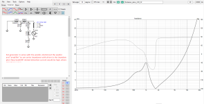
Here is example to your question, AllenB already linked to similar. A 2nd order low pass makes convenient impedance peak just above low pass frequency which likely helps with the distortion already, but it is so gradual low-pass the breakup peak would still be obvious in frequency response and could still benefit from a notch filter to knock it down.
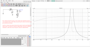
And, to notch the peak with a series notch in parallel with driver would provide low impedance circuit around the low pass filter for the backEMF current to flow, this is counter productive so you'd still want the parallel notch in series with the driver to maintain high impedance, and have effect on frequency response.
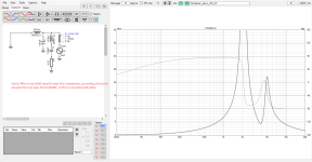
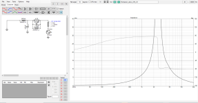
Anyway, you should be fine as long as you pay some attention to this kind of stuff, are aware of this distortion mechanism so don't accidentally use worst possible xo for example, but can take this stuff into account. For example, make a good frequency response happen, then check out what the impedance looks like, if it's above zero it's already better than if it was an active system, voltage amp with short wires straight to woofer. If it near zero, perhaps see if you can juggle things a bit.
For active system simplest thing is to add series inductor to make one pole of low pass, and then tailor the acoustic response with active EQ.
One could add another notch for breakup if wanted.

Last edited:
Haven’t simulated it yet, but I think an uneven order lowpass would be a good alternative to the series LCR.
Maybe or maybe not. The capacitor and the second inductor from a third order LPF for instance form another series LC circuit that is in parallel with the driver. Depending on its pole frequency it may not be helpful in reducing distortion.
Regards
Charles
Regards
Charles
- Home
- Loudspeakers
- Multi-Way
- Passive filter attenuation of breakup-related distortion in a woofer
